The BC-1421A Ground-radio
View of a very solid receiver. It is the successor of the BC-639A, the differences are minimal. In the BC-1421A a relay is used which, when energized, shorts the signal-grid of the LF power tube to ground . Probably it was controlled by the transmitter. Furthermore, a double diode, 6H6, is used as a noiselimiter.The inside of the receiver can be found in the BC-624. The American radio BC-1421A is the replacement of the English R1132 receiver.
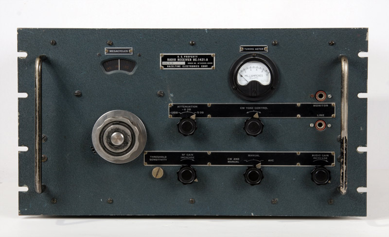
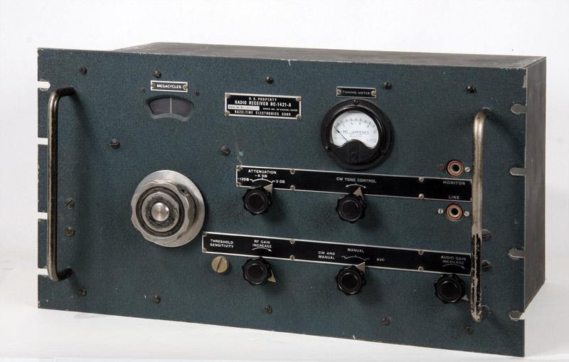
The front. The color is a little green / blue. This version was used by the Navy, also black colored types have been used.
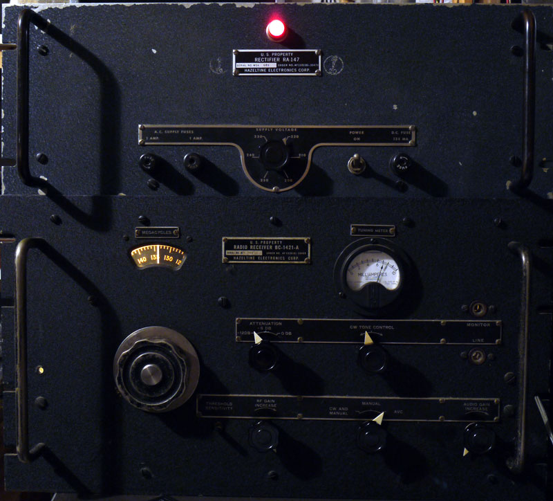
A black one during working conditions.
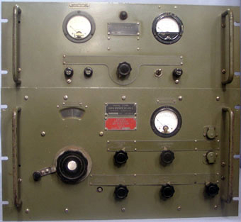
This is the American / British Receiver BC-639 / R.5032A with powersupply.
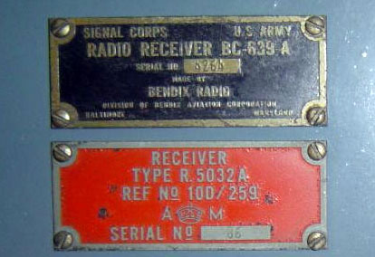
The nameplates.
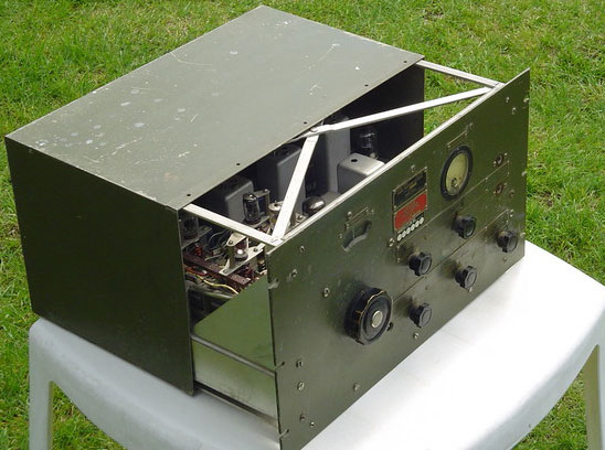
A green BC-639. The type of sender was the BC-640.
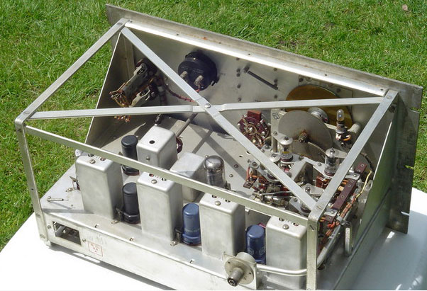
Inside of the BC-639, with Jones-plug for the power-supply and a PL-259 antenna-connector.
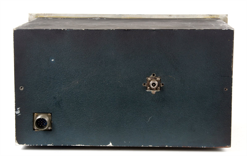
The back of the BC-1421A with the connection for the power-supply and line-output and the antenna-connector. (Here a N-connector, there were also versions with the PL-259 connector.)
The superheterodyne receiver was used as ground-radio-station for communication with aircraft in the frequencyband 100-156 MHz.
The receiver-valves:
| Name | Type | Function |
| RF | VT-201 (6AK5) | High-frequency amplifier |
| Mixer | VT-203 (9003) | Mixer |
| Osc. | VT-202 (9002) | Local oscillator |
| Doubler | VT-203 (9003) | Frequency doubler |
| 1st. IF | VT-211 (6SG7) | First intermediate frequency amplifier |
| 2nd. IF | VT-211 (6SG7) | Second intermediate frequency amplifier |
| 3d. IF | VT-211 (6SG7) | Third intermediate frequency amplifier |
| Det. Audio, AVC | VT-103 (6SQ7) | Detector, AF-amplifier and AVC. |
| 2nd Audio | VT-152 (6K6) | AF- poweramplifier |
| CW.Osc. | VT-211 (6SG7) | Beat FrequencyOscillator |
| Noise Lim. | VT-90 (6H6) | Noiselimiter |
The whole in a aluminum cabinet weighs about 19 kg and is built for eternity. Solid construction and components.
The sensitivity of the receiver is also very good. No wonder that this radio was used in so many radiosystems.
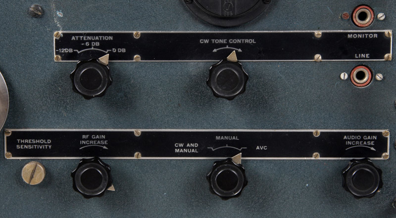
The controls.
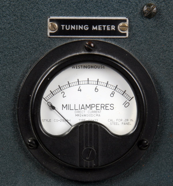
The power meter, which, in fact, gives some indication of the strength of the received signal.
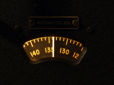
The receiver operating and tuned to 134 MHz.
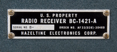
The plate with serial number. Manufacturer Hazeltine Electronics.
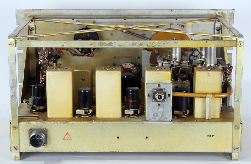
The back with the four! IF-transformers. The tubes with clips nicely fixed. The pipeline on the right is the connection between the antenna-plug and first RF stage.
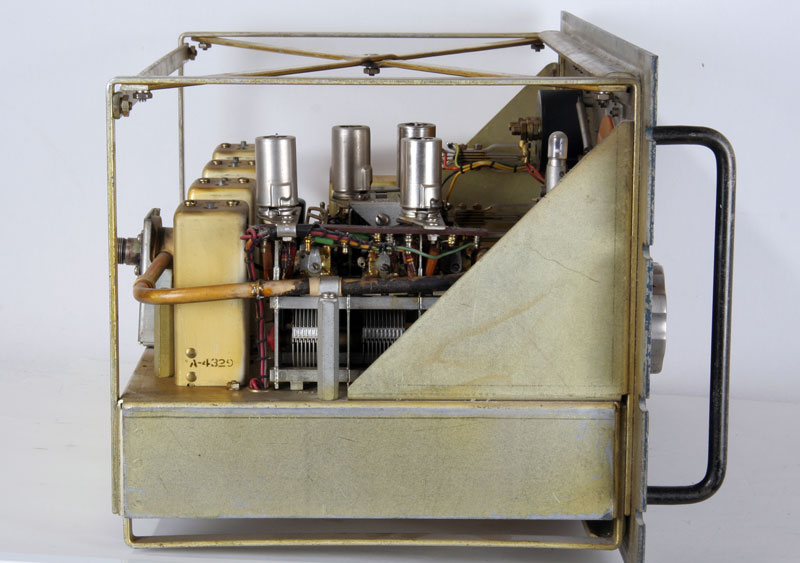
On the left the RF section. The tubes are equipped with metal shielding caps.
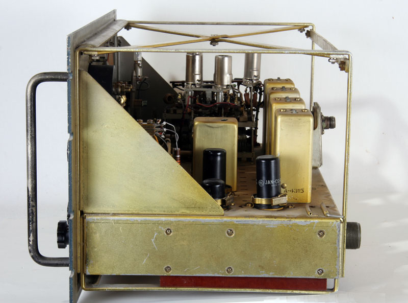
The right side, the detector, noise-limiter and BFO.
An orderly and a sturdy frame.
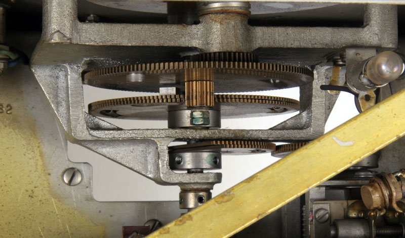
The gearbox of the tuningmechanism.
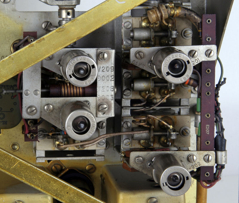
The RF section, on the left the oscillator and the doubler and on the right the RF amplifier and mixer.
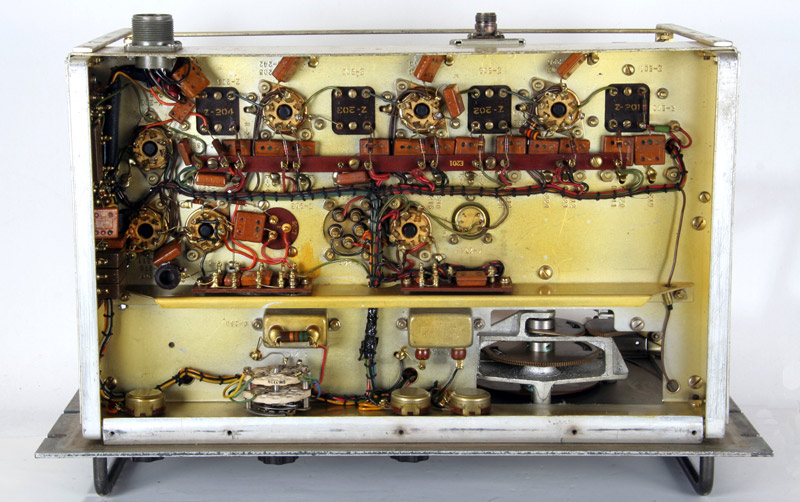
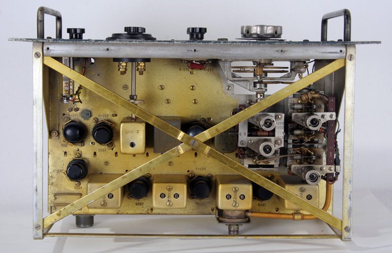
The underside, with lots of space.
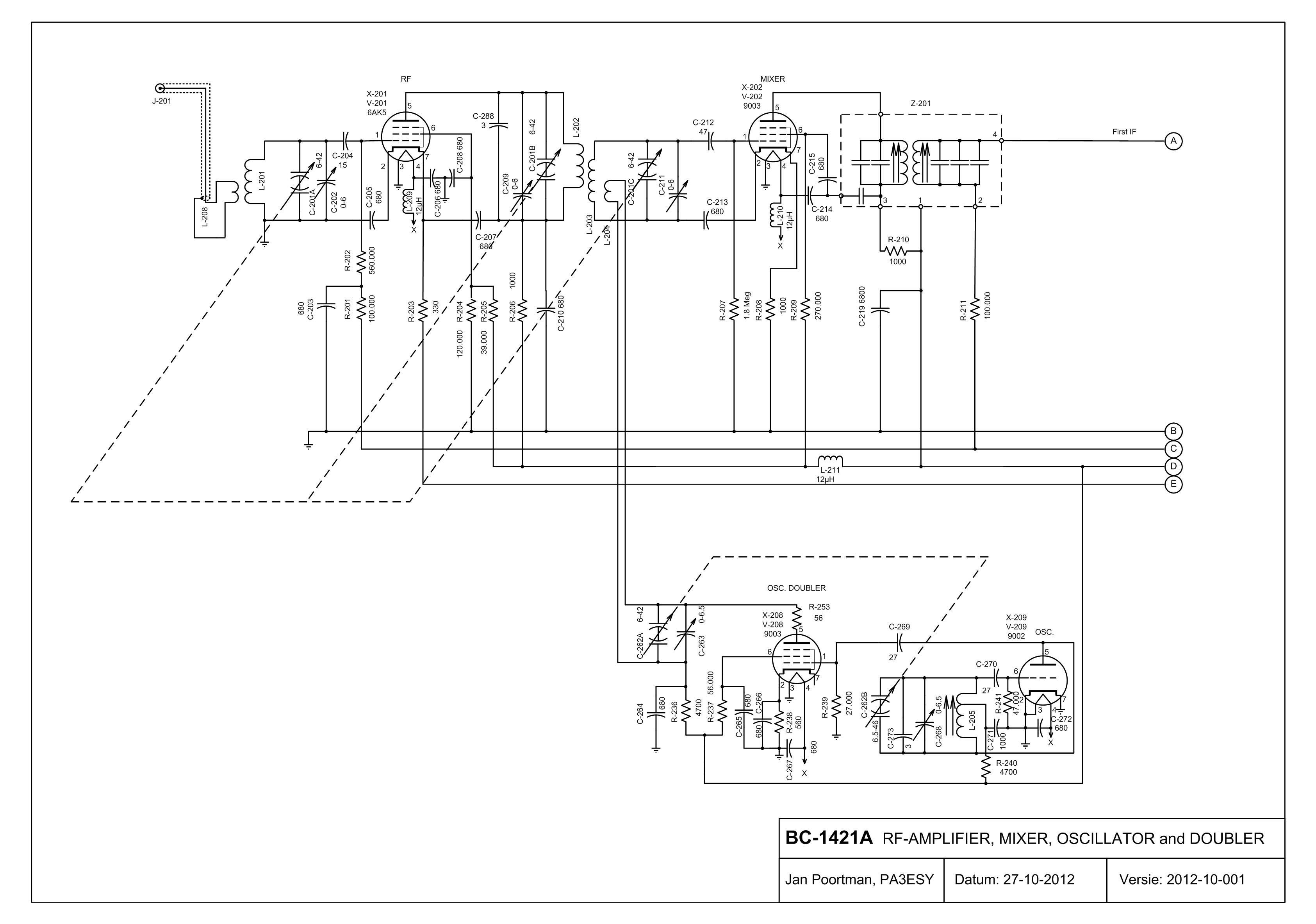
Below the electrical circuit of the BC-1421A in three parts. By clicking on the pictures you will see a larger size.
R.F.stages with local oscillator , doubler en mixer.
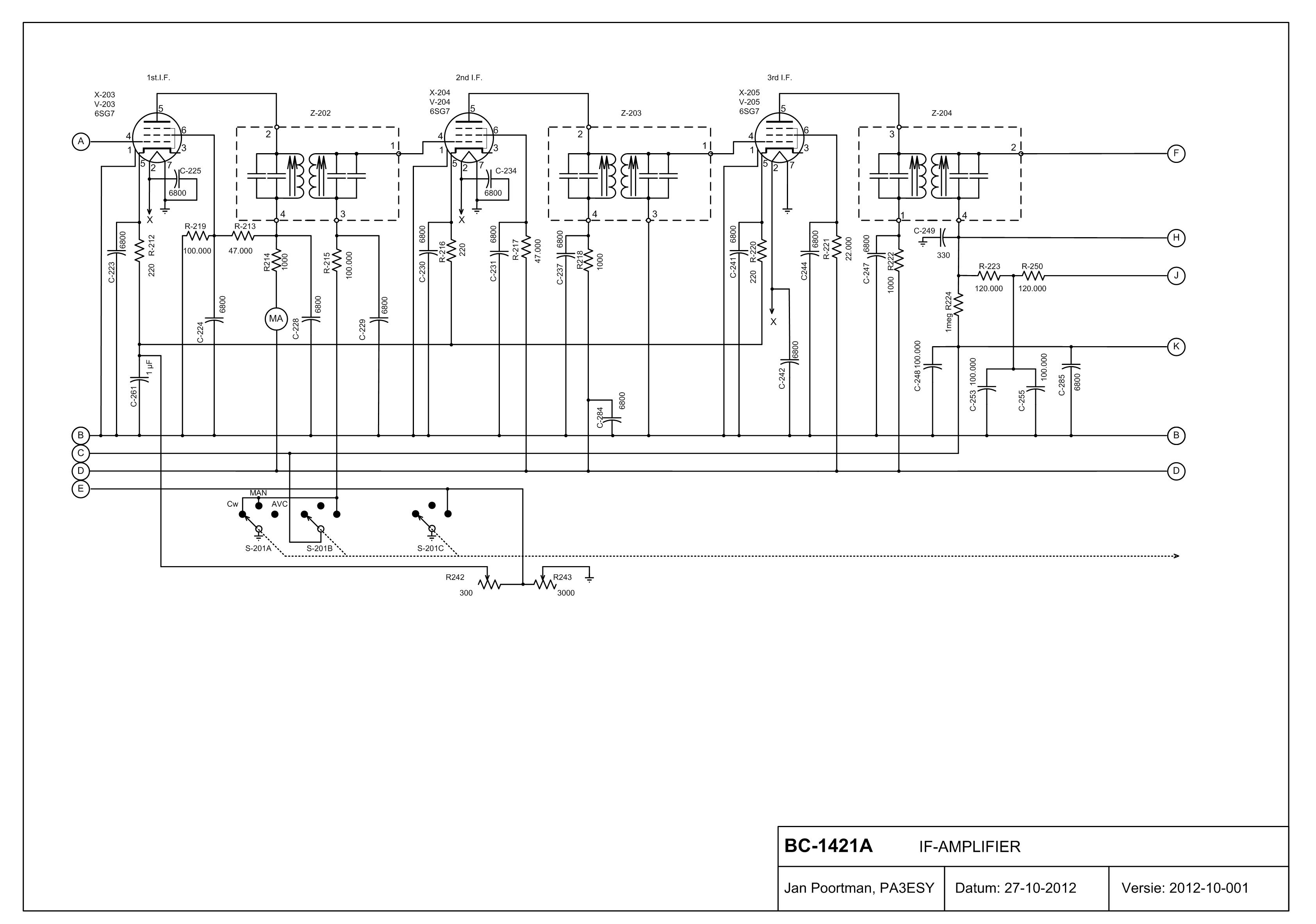
IF-Amplifier.
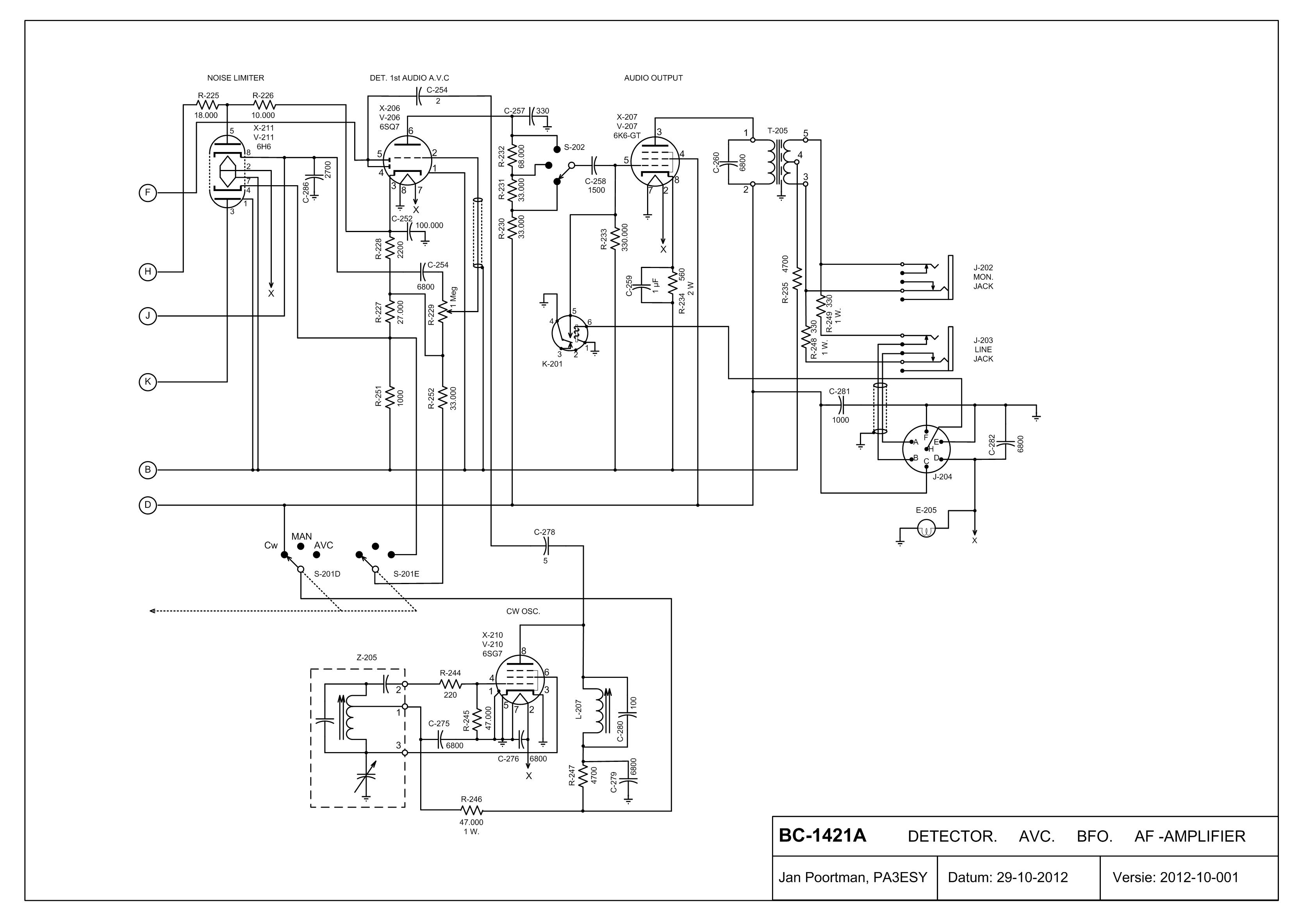
Detector, BFO, AVC and AF-Amplifier.
The power-unit RA-147
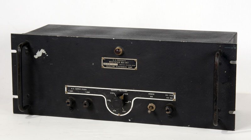
A fairly heavy duty power supply.

The controls.
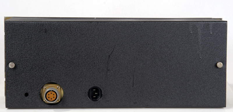
The back with modified line-connector. (This with regard to the safety)
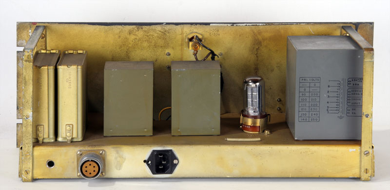
The open back side with at the right the huge power-transformer, in the center two chokes and on the left the smoothing capacitors.The rectifier is a 5Y3G.
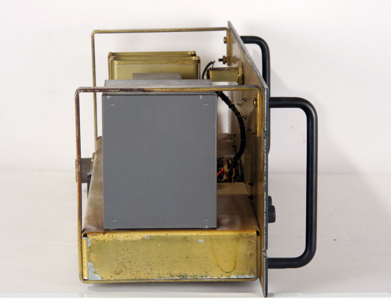
The top.
The power transformer.
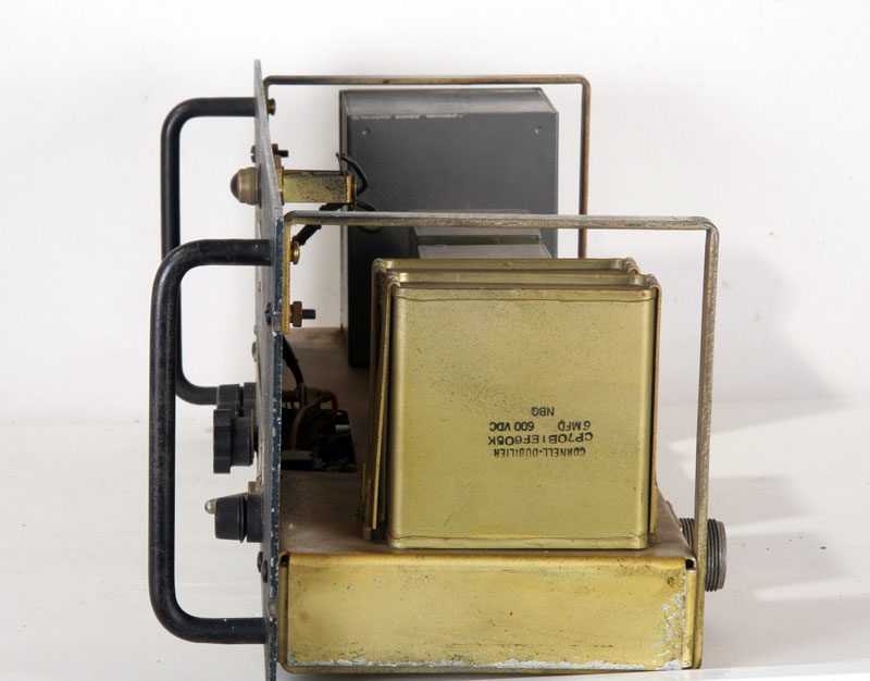
The considerable smoothing capacitors of 6 muF and 600 V. DC.
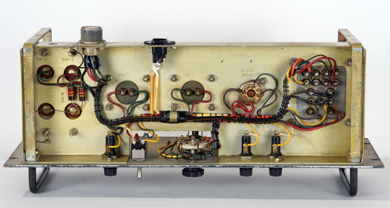
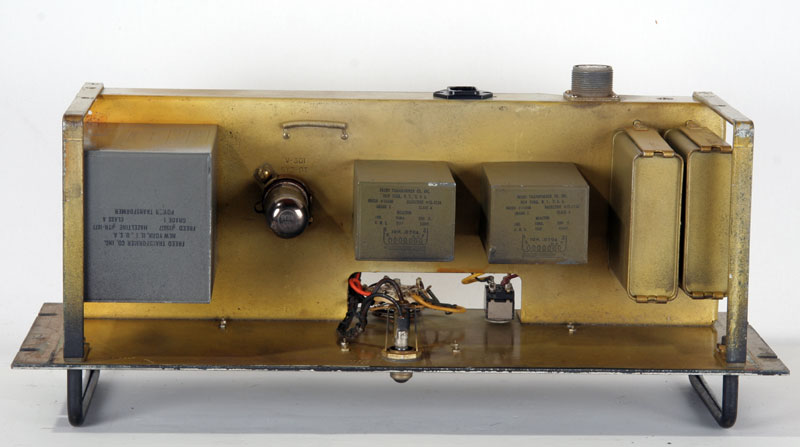
The nicely wired bottom.
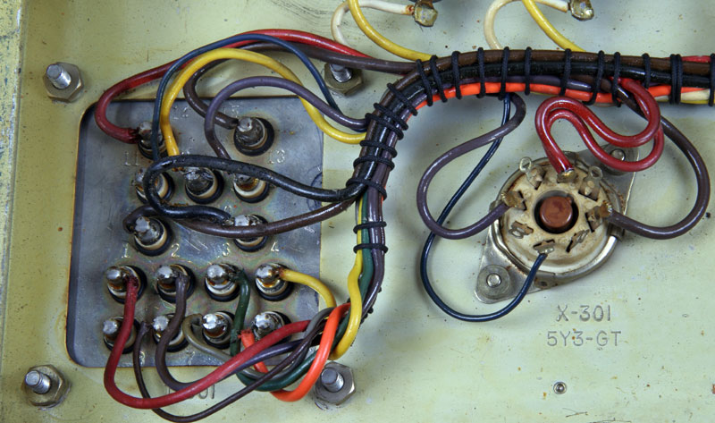
The terminals of the transformer and the rectifier tube.
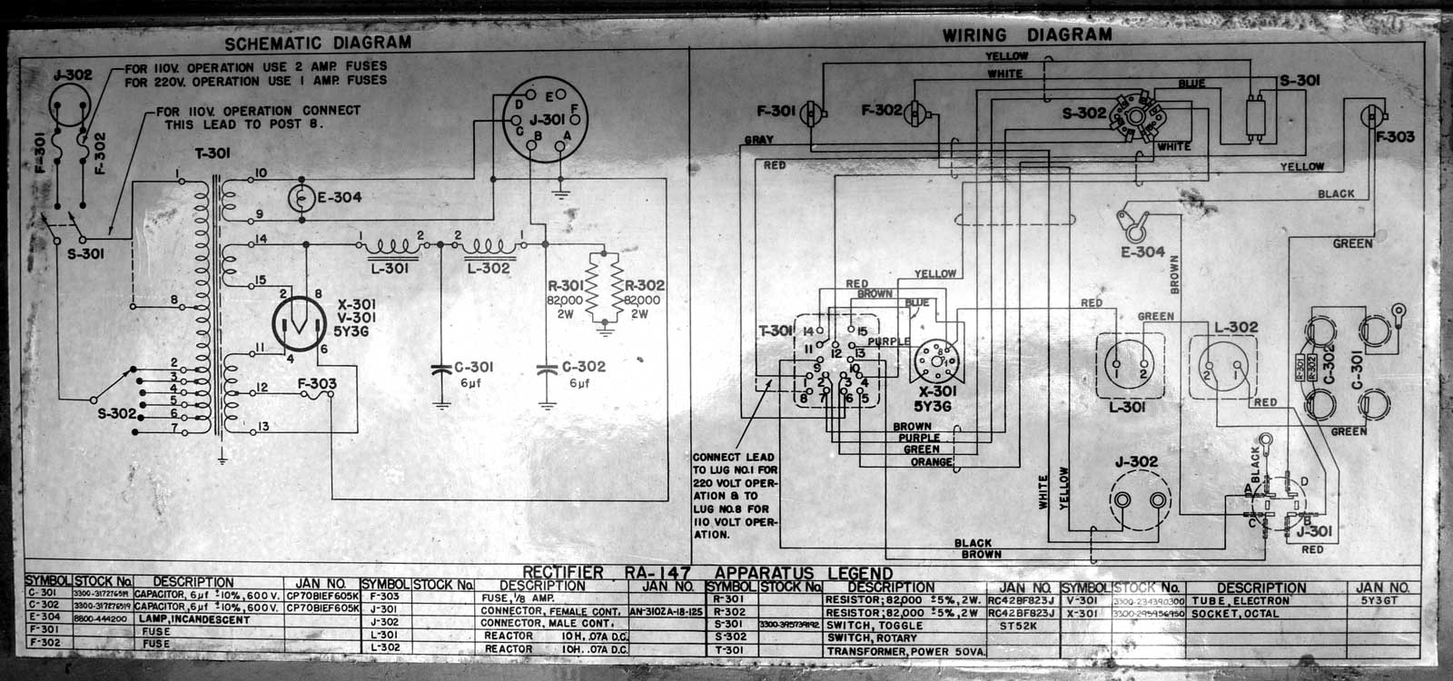
The schematic of the RA-147. For enlargement click on picture.
,For enthusiasts: The maintenance instructionsof theBC-639A