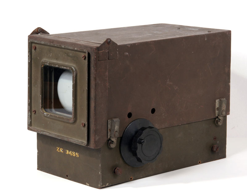
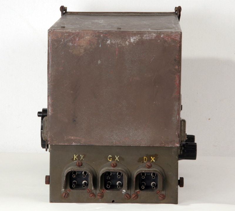
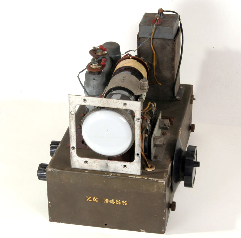
On a radio-fleemarket in Rosmalen in the Netherlands, in March 2004, I bought a nice green British box which should include a cathode ray tube.
Nobody was able to tell me what it was exactly. The only thing they knew was that the instrument appeared in Belgium some years ago.
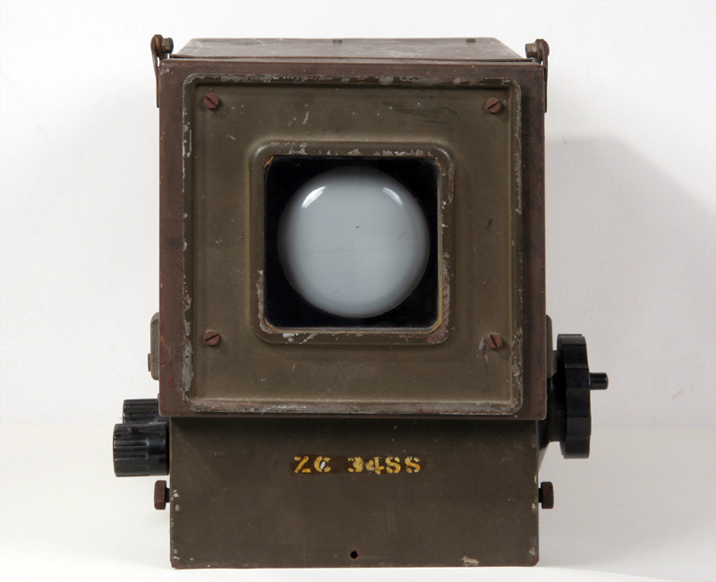
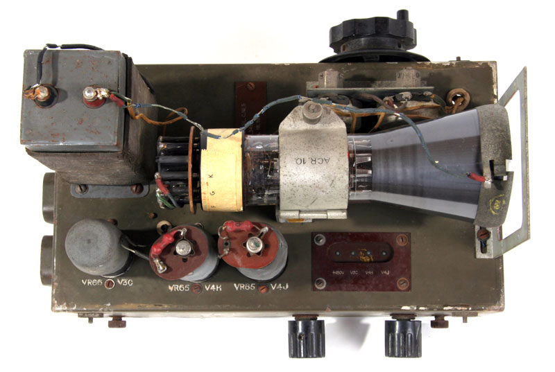
So this is the indicator, in front of the CRT was a scale.
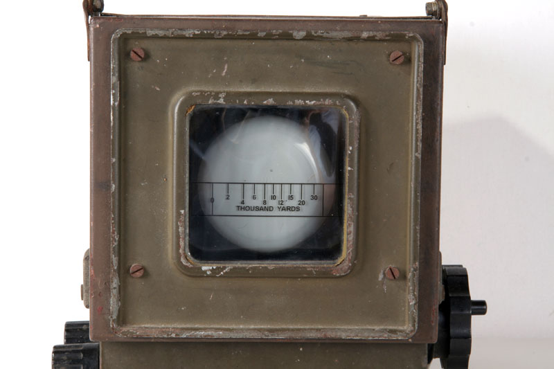
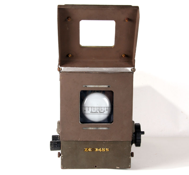
Closed door with scale.
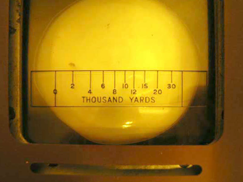
This is a photo of the scale. The picture is made of S/L C. Nr. 5, part of the collection of Jan Bodifee. Signals Collection '40-45'
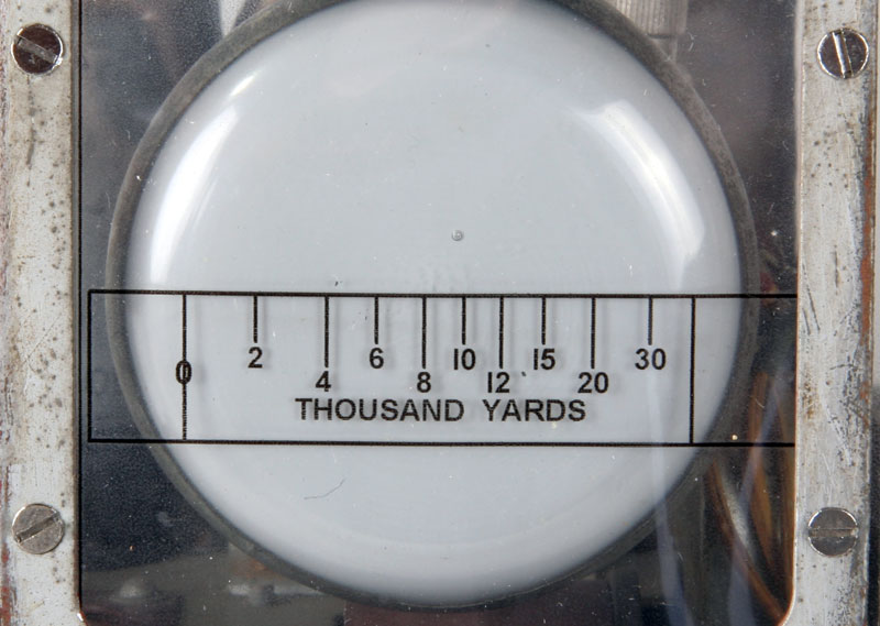
The replica-scale, the accuracy is sufficient enough...
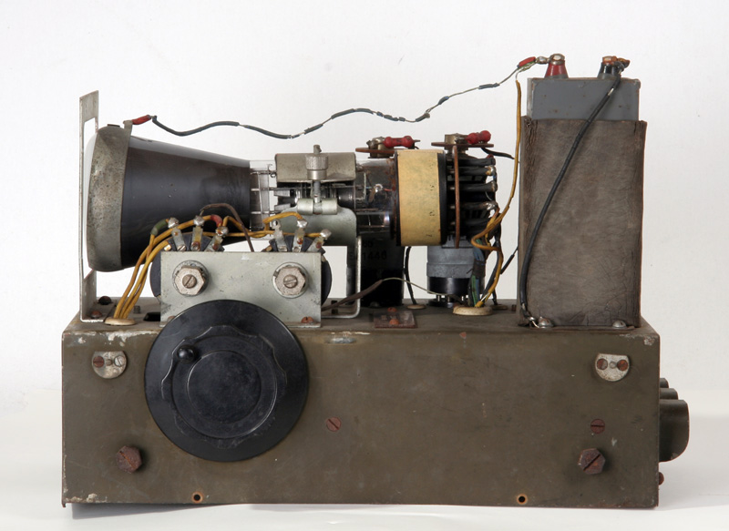
The big knop is coupled to a big, wirewound potentiometer, no function is mentioned.
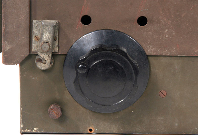
Detail of the large knob on the right side and the two holes for the adjustment of two potentiometers.
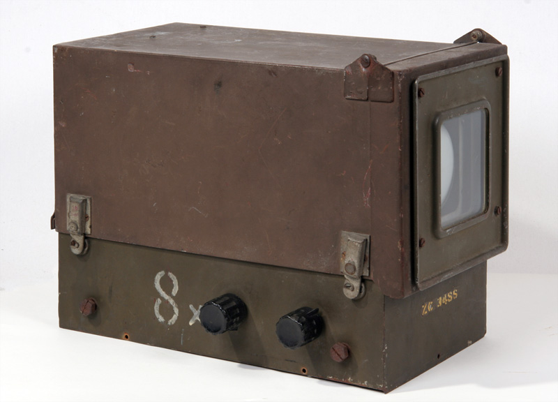
The other side is also provided with two controls, probably for brightness and focus.
Door opened.
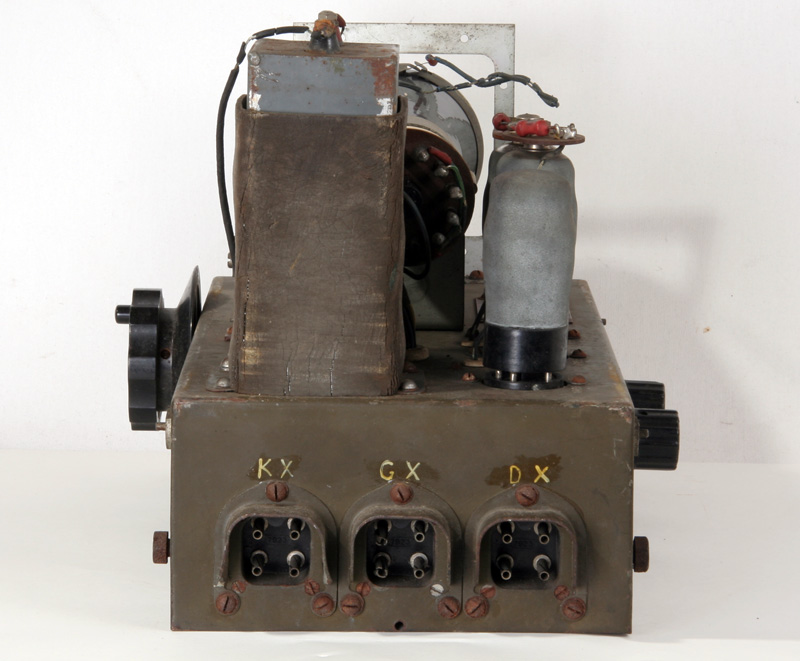
The back has three connectors,the same as the microphone of the WS18-set, the meaning of KX, GX and DX is not known until now
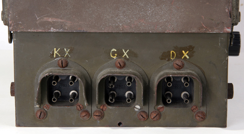
Detail of the connectors.
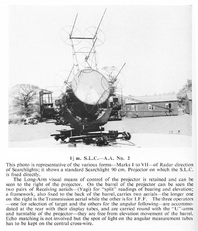
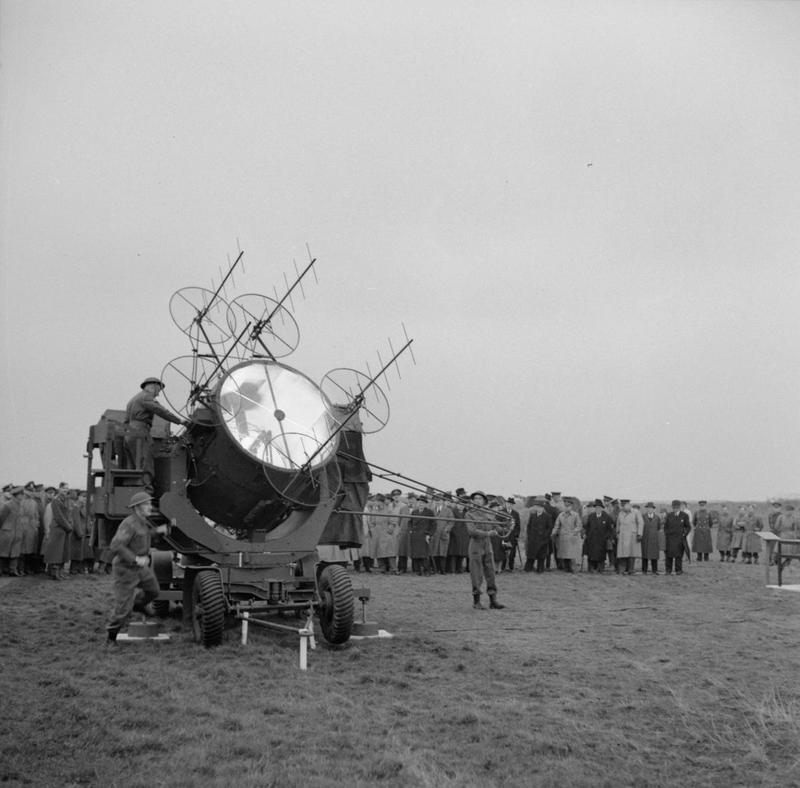
Louis Meulstee sent me the photo of the searchlight.
Three young British scientists — Chick, Eastwood and Oxford — first adapted a radar system to searchlights in June 1940. This equipment, known as SLC (searchlight control), or Elsie, significantly increased the liklihood that a passing aircraft would be "caught" in the beam. By 1942-43, the system (pictured above) became semi-automated and each searchlight (and antiaircraft guns) could be fitted with four-foot radar "mirrors" and could track a target automatically.
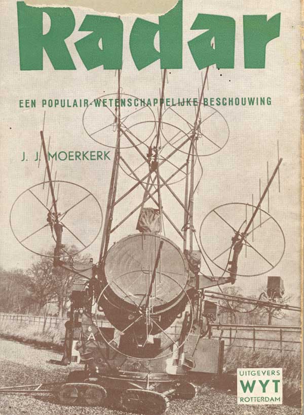
On the cover of the book above (Very interesting booklet) is the searchlight and just right below the right antenna, is the box of the S / L C. No. 5. There are three No.5 's mounted to the device. Hence perhaps the great Belgian numbers. The indicators are mounted on the U-arms of the light, so they dont move with the elevation of the light.
In Part 2 of "Het Jongens Radioboek" by Leonard de Vries,on photo sheet 3 is a picture ( 8 ) of the indicator, with the following text: "Radar antennas with a searchlight of the flak.
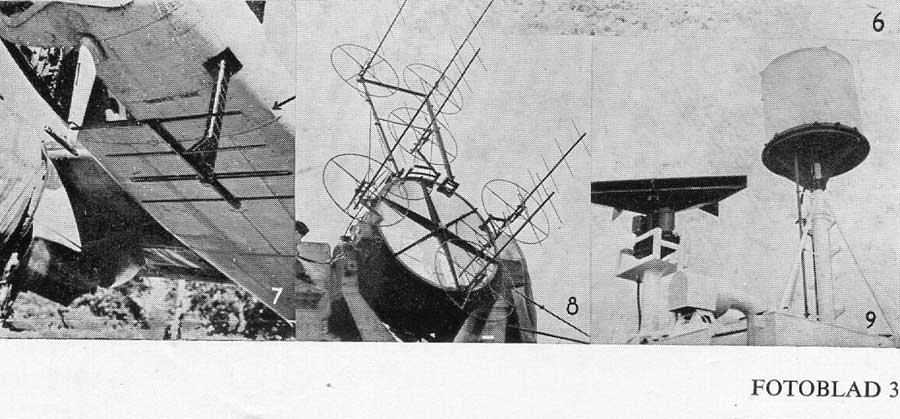
Transmitting and receiving antennas substantially have the same shape and dimensions. The number of directors (dipoles, that are mounted in the actual antenna) is much larger). Such an antennasystem is known under the name of Yagi antenna. The searchlight is switched on, when the antenna is heading for the best position to the detected aircraft.
These were indeed very useful notes for the coming radioamateur......
A demonstration of the "ELSIE"
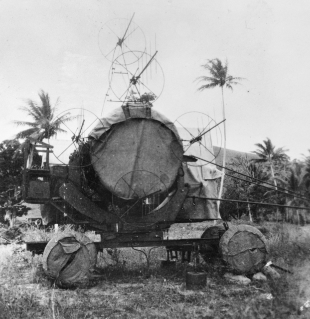
A sleeping searchlight, it was possible to activate the light within minutes.
Front view with the square window, for the attachment of the scale.
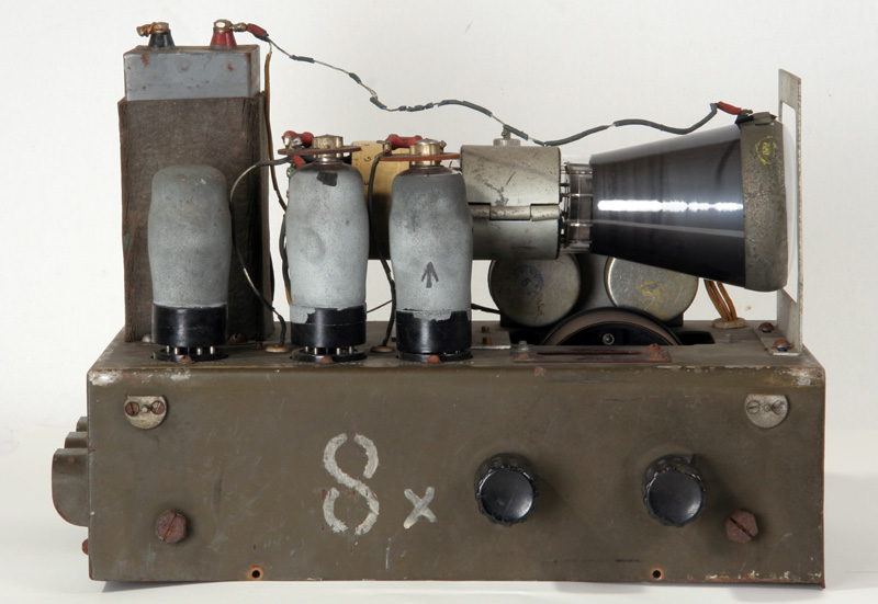
On the left side the tubes, VR3C = VR66, VR65 and V4K = V4J = VR65. The letters behind the tube-number indicate that this is a
is part of a larger set. When the same tube type multiple was used, they were numbered: E.g. V1A, V1B, V1C etc.
On the right two adjustmentresistors and the large control.
The large tower, left, is a blockcapacitor for the high voltage of the CRT.
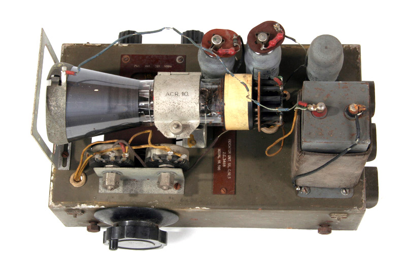
Top view from the right side.
The same but from the left side.
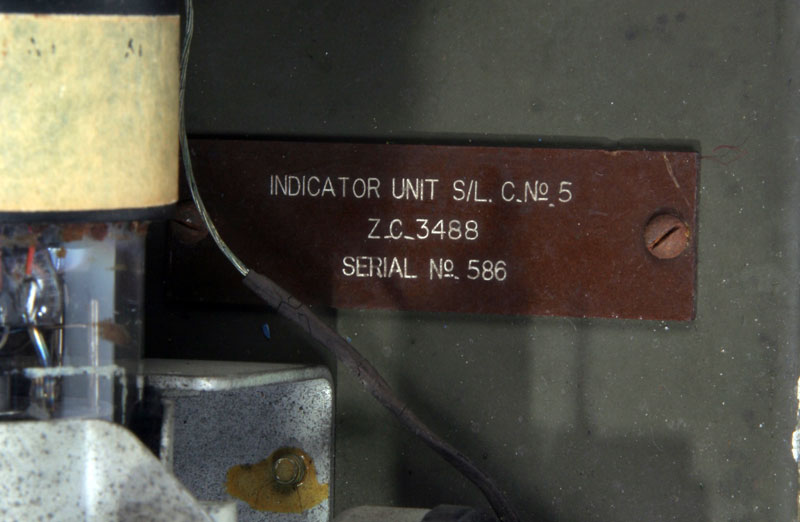
On the type-plate you can see the designation S / L, this means Searchlight.
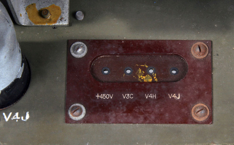
Four test-points for voltage, 450 V and points of the three other tubes, but what???
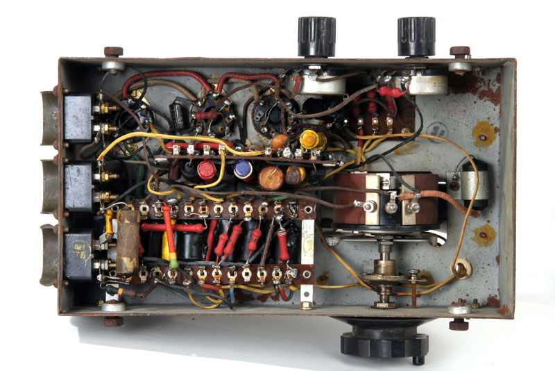
On this picture you can see the bottom. What is striking is the use of Philips resistors, the red ones and the black Philips capacitors.
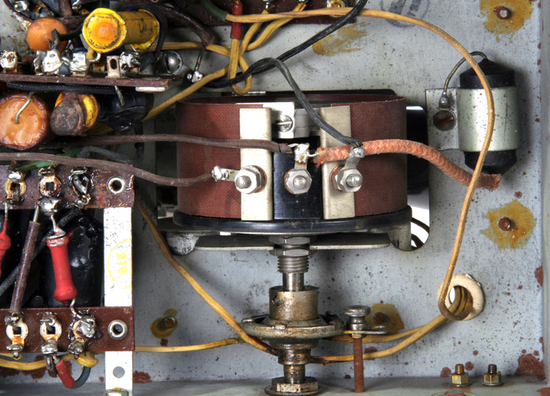
The large wirewound potentiometer with ball-drive
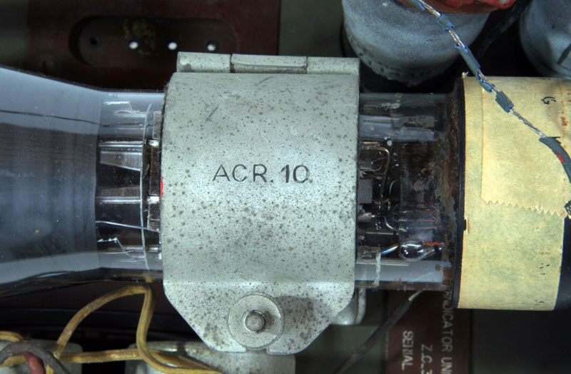
The cathoderay-tube, an ACR10, I bought via the internet. Whether it works is not known to me, I have no illusions the indicator ever to make it run, even getting the rest of the searchlight and the guns will be tricky. And I have not enough space in the garden.
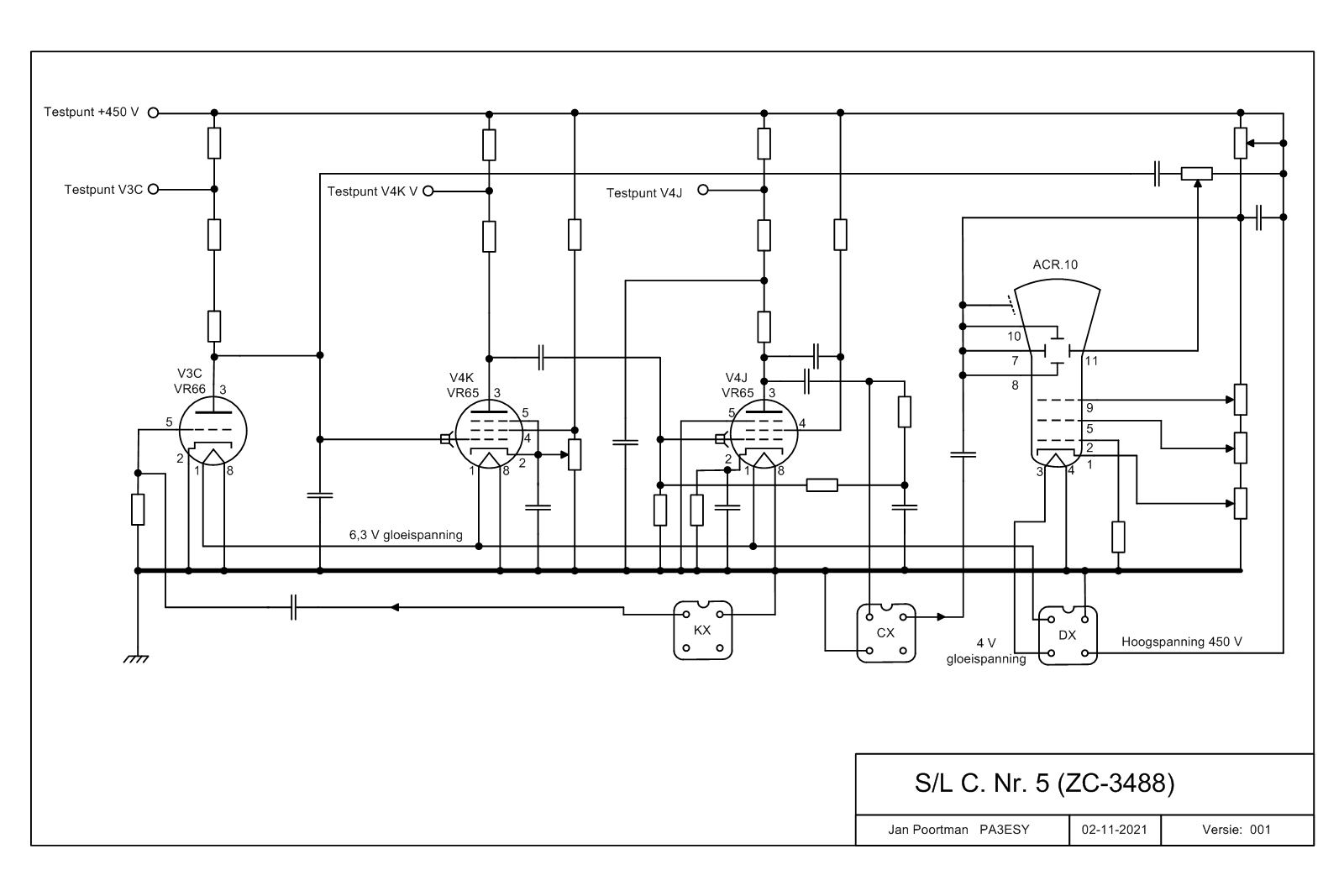
Circuit-diagram, I have no values of the components.