Wireless Set No. 22 ( ZA 11964 )
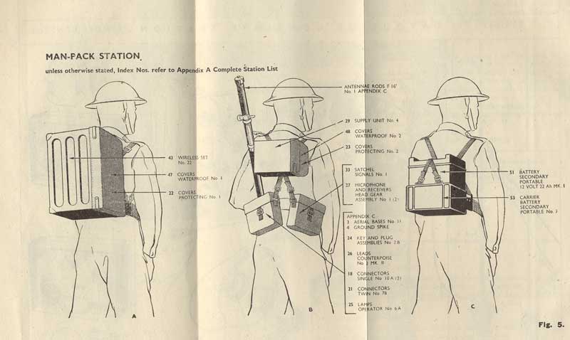
The WS-22 was used as a "general purpose" transceiver with low power. The device has two communication methods, radio telephony and CW. Furthermore, the set can be worn as a "manpack '. It can be mounted on a kind of trolley or, especiallyfor use in vehicles. There is also a mountingsystem for donkeys. Frequency range 2 - 8 Mc, divided into two bands, 2 - 4,5 Mc and 4.5 to 8 Mc.
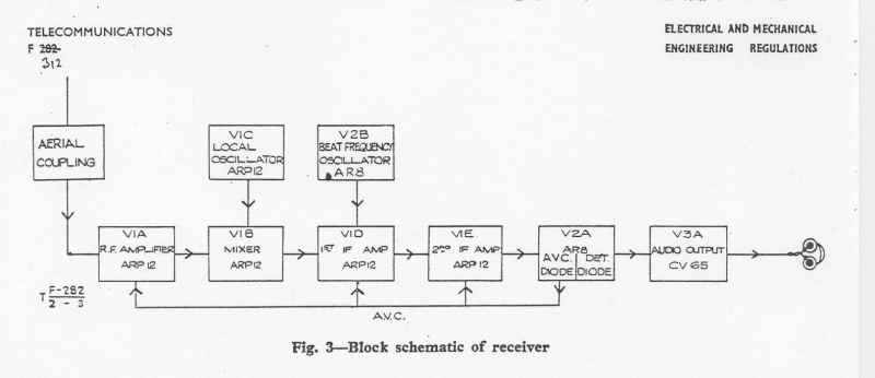
The receiver is a normal 7 tube superheterodyne with an RF stage, a separate local oscillator, mixer, two IF stages on 465 kc, diode detector and a LF amplifier. There is a BFO for reception of undamped telegraphy present. The sensitivity is 3 microvolts for 10 mW output and signal / noise ratio of 15 db.
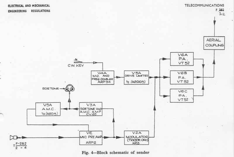
The transmitter consists of an oscillator with frequency doubling, a drive-limiter and an output stage with three parallel power tubes. For the modulator, two receiver tubes are used. The set is housed in a steel case with a separate vibrator power unit. There is also a dynamic headphone and microphone used. As an antenna a 12ft. rod (mobile business), 34ft. bar (static mode) or 140 ft. wire can be used.
The distances that can be covered are: 10 miles in R / T, 20 miles in CW with 12 ft. rod and with the 34 ft rod about the double range. The current consumption is, depending on the use, between 2.2 and 4.6 A. at 12 V.
For more information on the set, see the books by Louis Meulstee or visit his website "Wireless for the Warrior": The information provided on these pages is mainly consists of pictures and short descriptions. A website with lots of pictures is under this link: Wireless Set No 22 & Accessories.
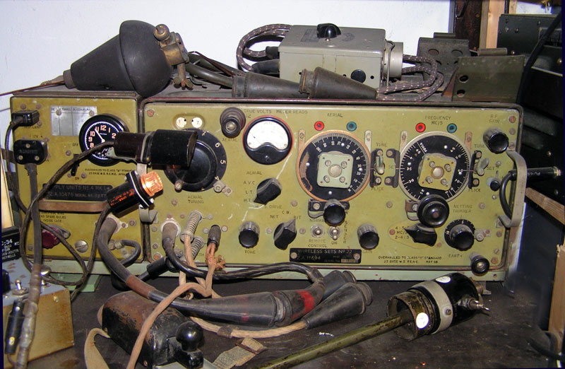
De set as it is in my shack.
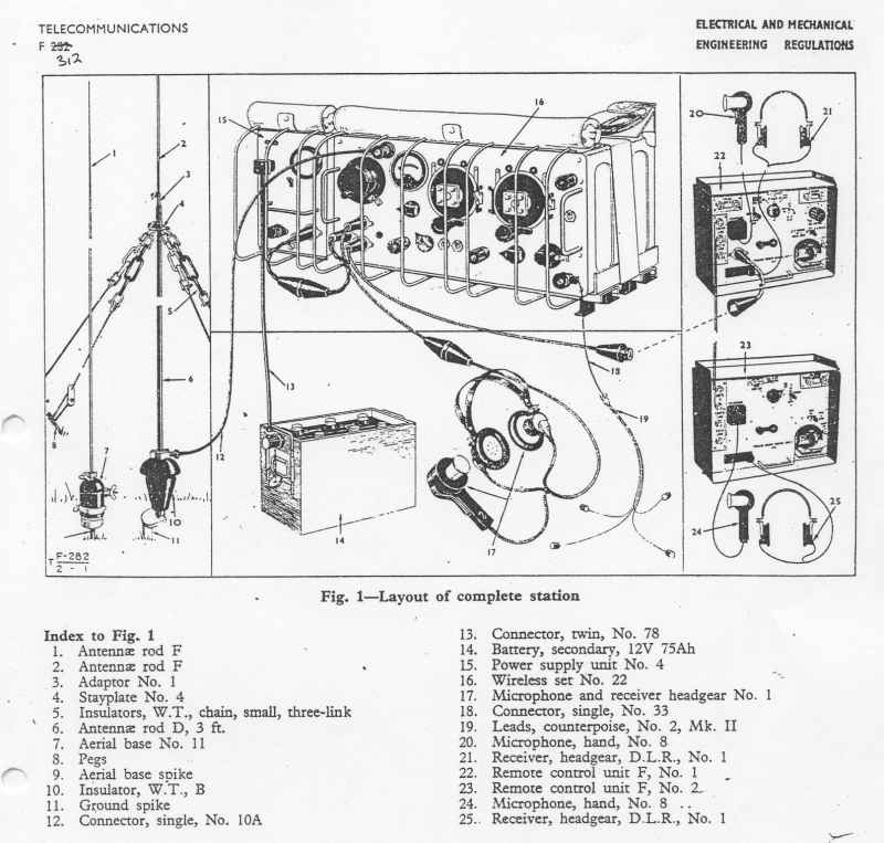
In the image below, the entire station.
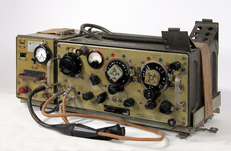
The WS-22.
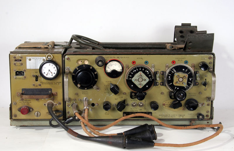
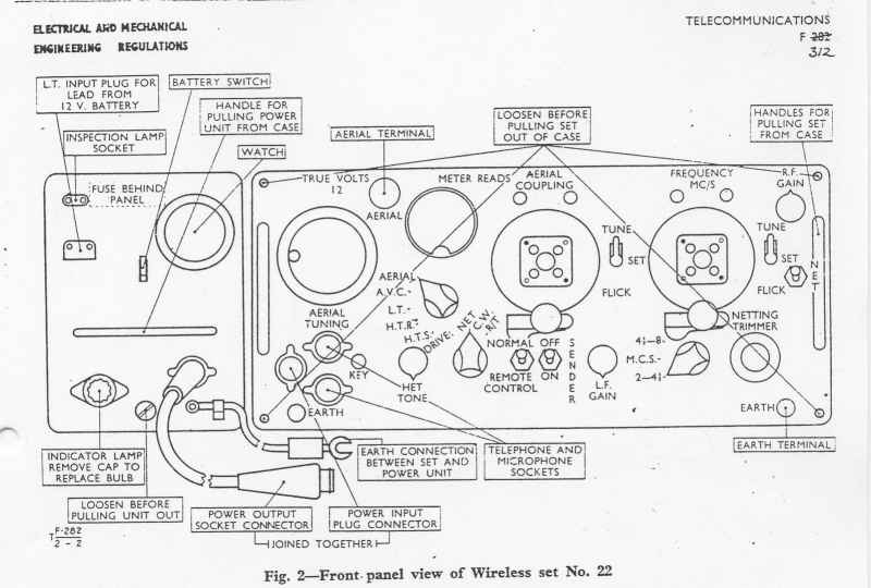
Front-panel-view.
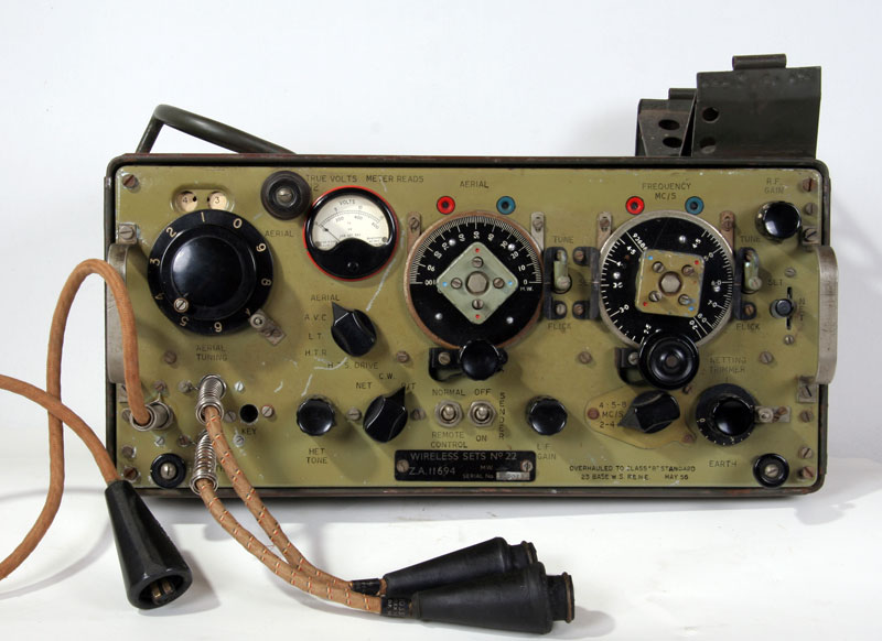
Transmitter-receiver.
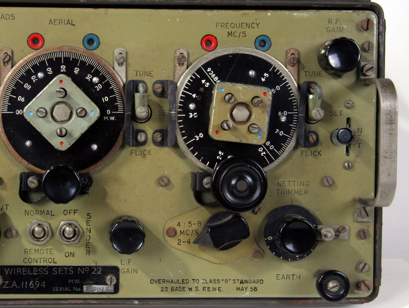
The two scales of alignment and further operation.
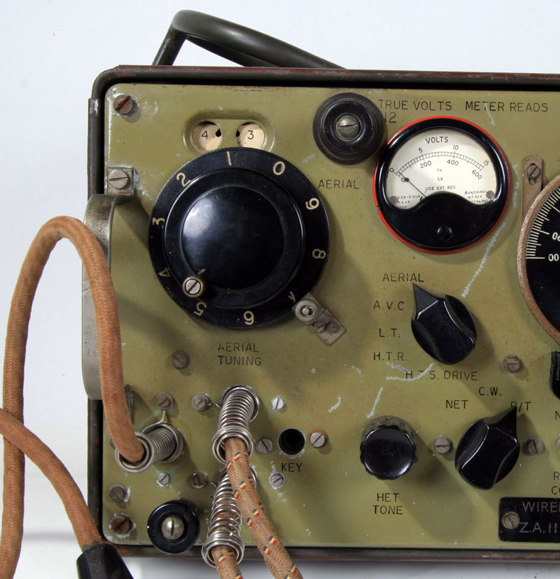
Button on the roller inductor and instrument for various indications ..
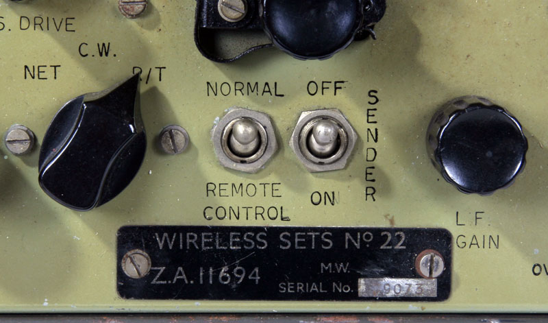
Model plate serial number.
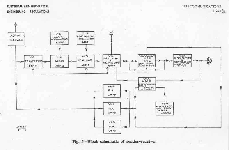
The complete block diagram is shown below:
The block diagram for the receive mode:
The block diagram for the send mode:
The tubes utilization:
| Schema ref.nr. | Type | Function |
| V1A | ARP 12 | RF-amplifier |
| V1B | ARP 12 | Mixer |
| V1C | ARP 12 | Local oscillator |
| V1D | ARP 12 | 1.IF-stage |
| V1E | ARP 12 | 2. IF-stage, and modulator-pre-amplifier |
| V2A | AR 8 | Rectifier, receiv.. detector. Triode sender modulator |
| V3A | CV 65 | receiver-output, sender sidetone ampifier en AMC amplifier |
| V2B | AR 8 | BFO |
| V4A | ARP 34 | Master oscillator en frequency doubler |
| V5A | ARDD 5 | Automatic modulation control and drivelimiter |
| V6A | VT 52 | Sender-poweramplifier |
| V6B | VT 52 | Sender-poweramplifier |
| V6C | VT 52 | Sender-poweramplifier |
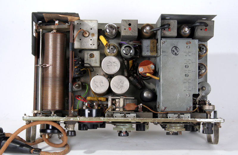
Top view.
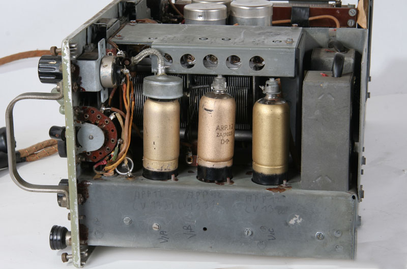
RF-stage, Oscillator and mixer
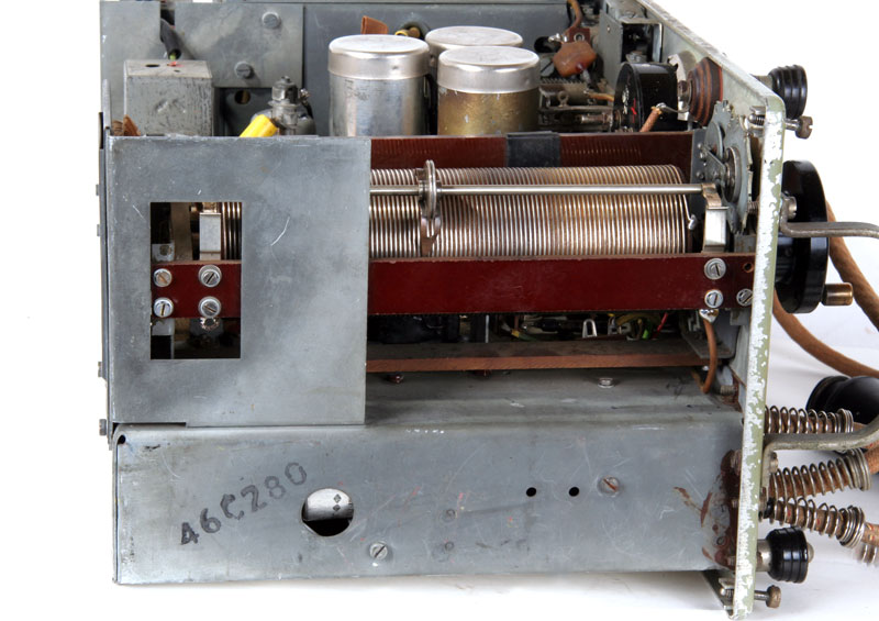
Left side with roller inductor.
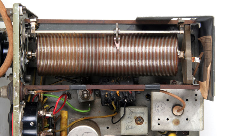
The roller inductor and antenna current meter
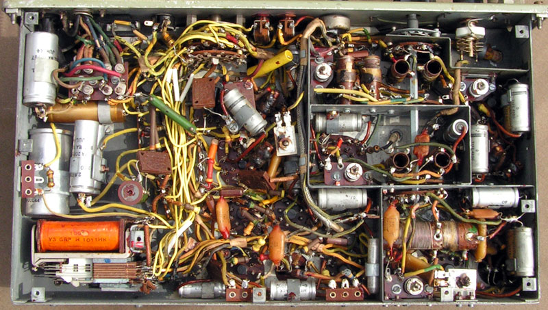
The underside.
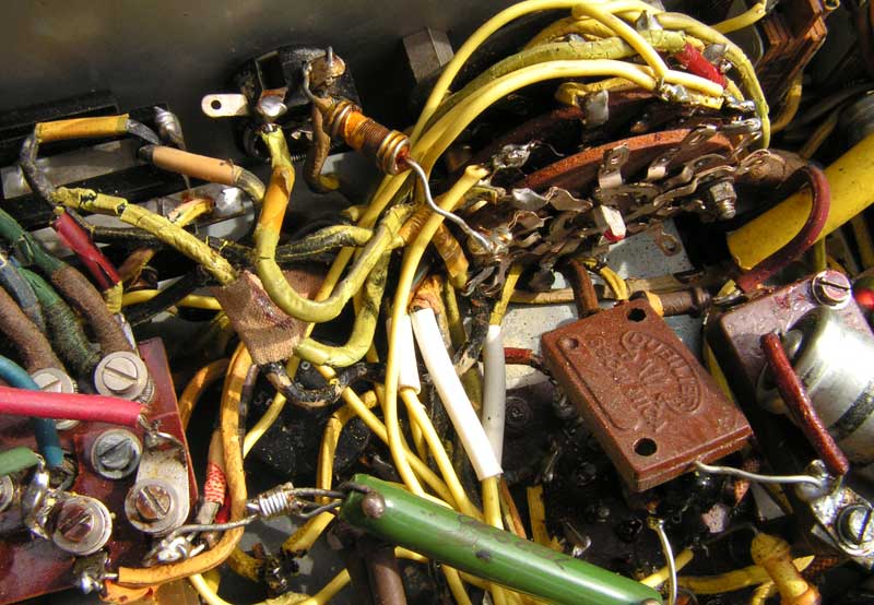
Detail of the wiring, a part of the yellow wires has already been replaced, and the rest is required to be replaced, see the broken insulation on the left-hand side.
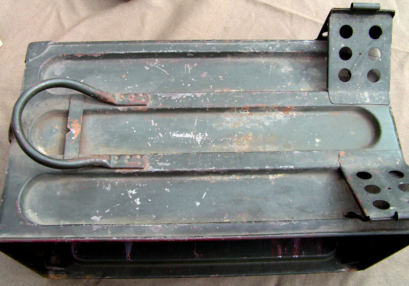
The cabinet of the set. Yummy for your back.
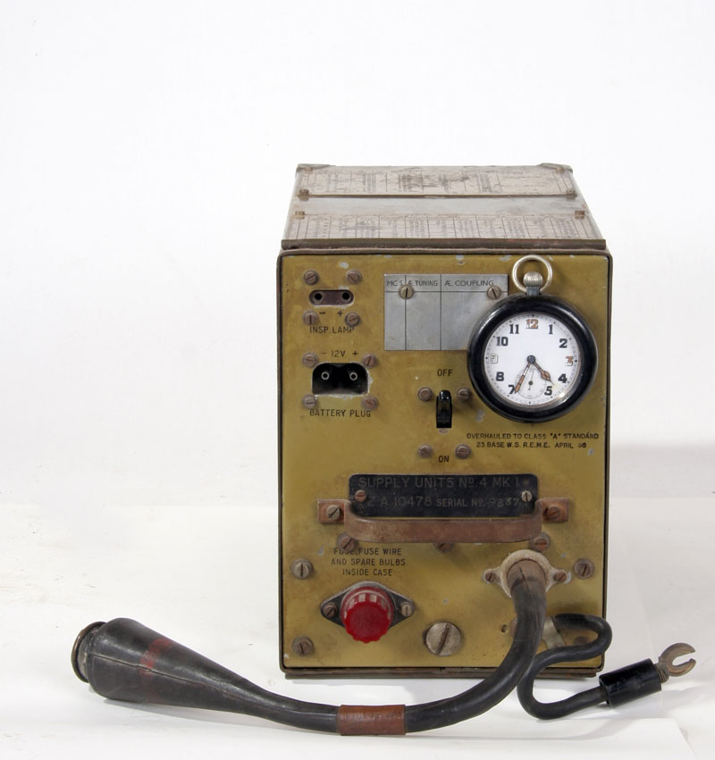
The vibrator power unit, with THE watch.
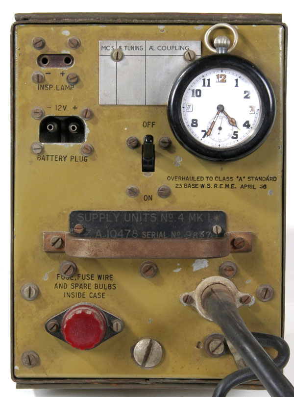
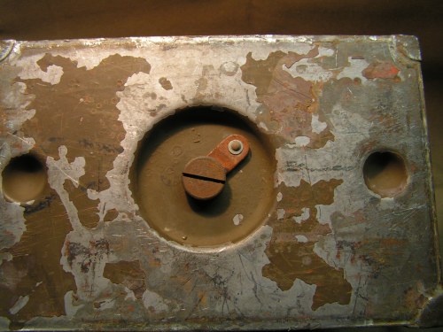
The front of the Power Supply Unit.
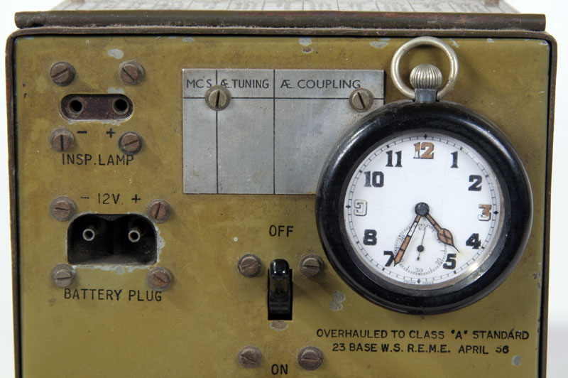
Detail of watch and connecting plugs.
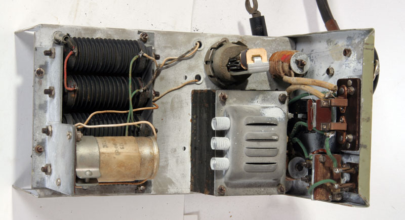
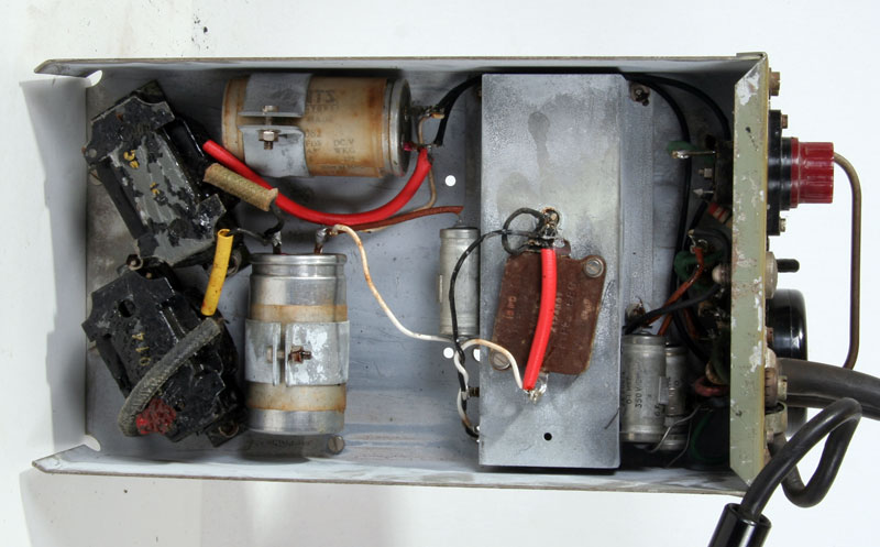
The inside of the unit.
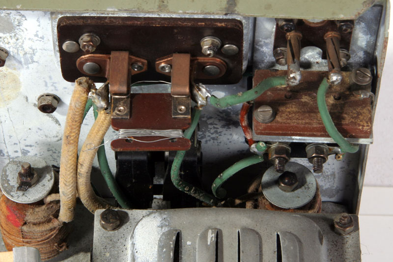
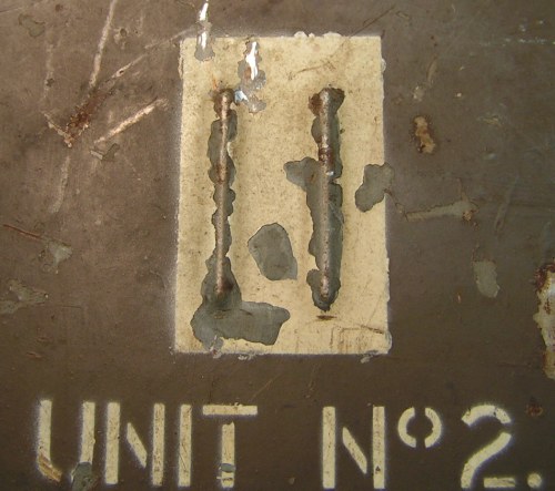
A detail of the fuse, the wire between the two copper strips is the fuse. The bobbin thread, on the right, is spare fuse wire.

The side with the uncanned vibrator.
The bottom of the power supply unit.
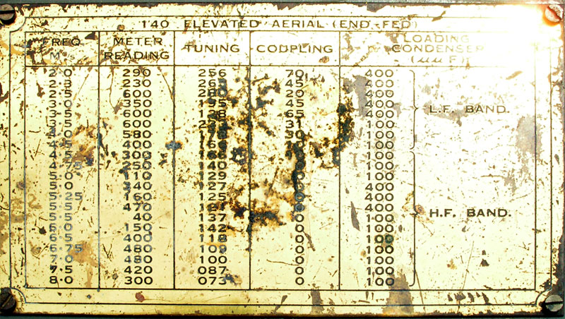
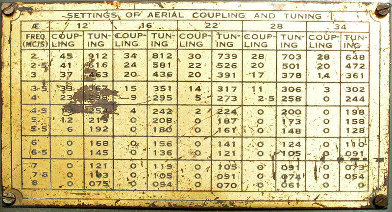
Antenna setting data on the body of the PSU.
As above.
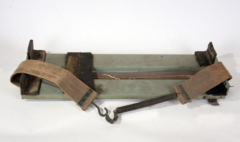
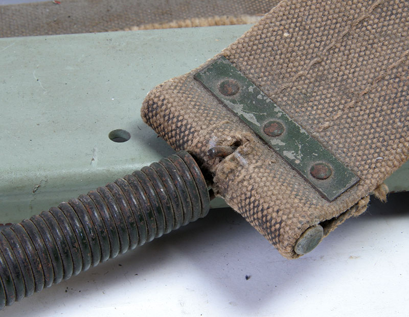
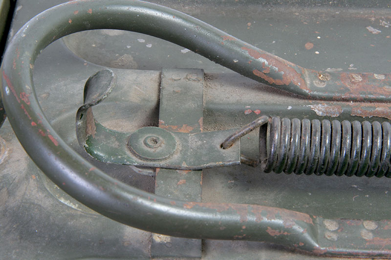
The mounting, with a quick mount system, a lot easier as the WS-19.
So the whole thing looks when mounted .
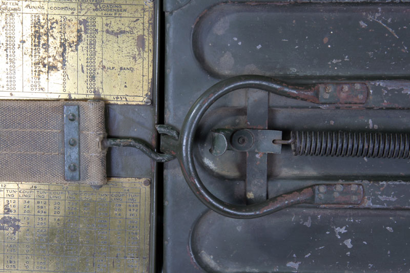
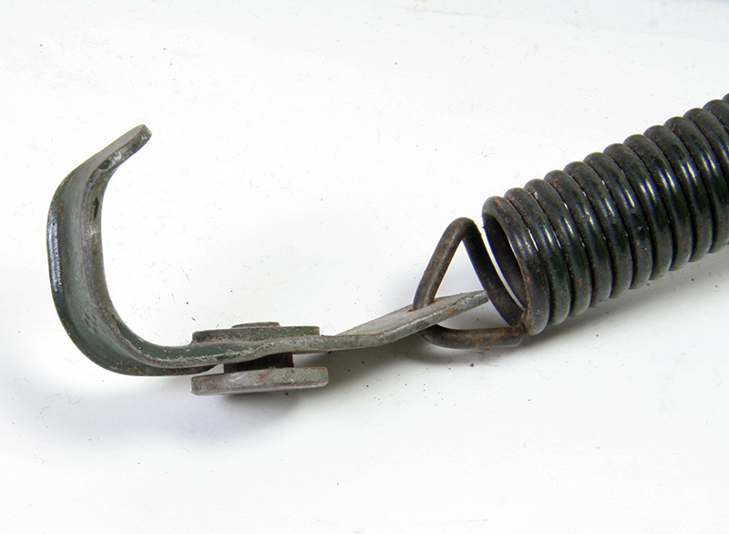
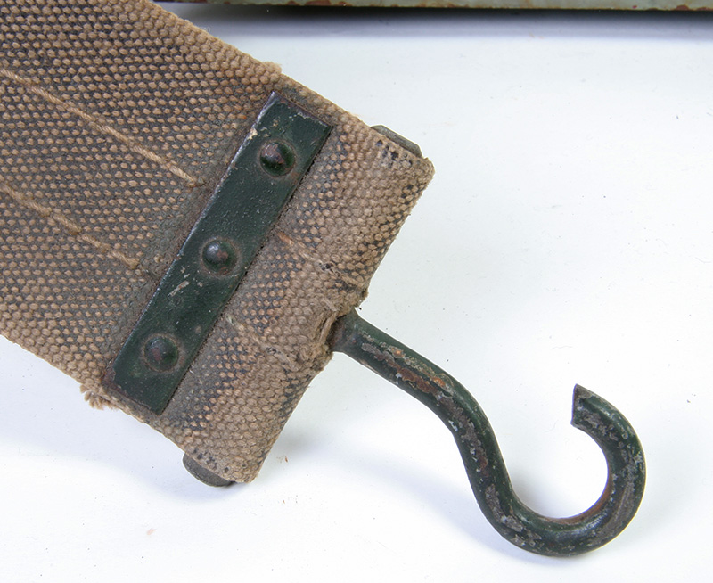
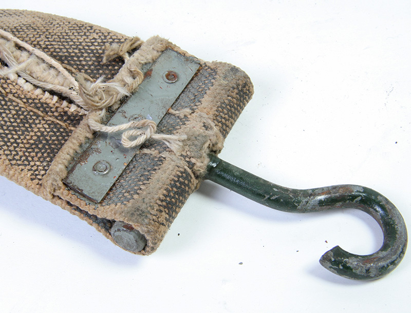
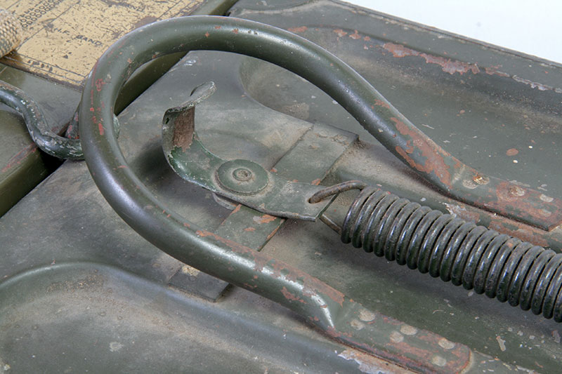
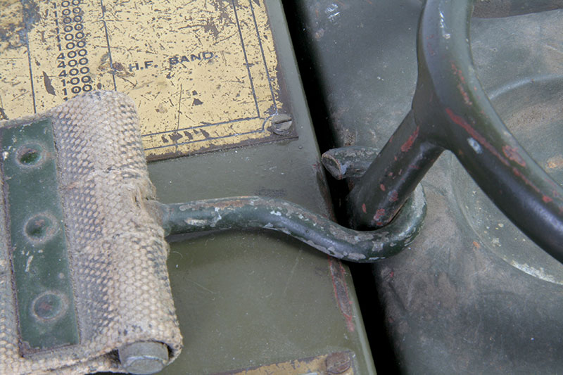
The spring with hook.
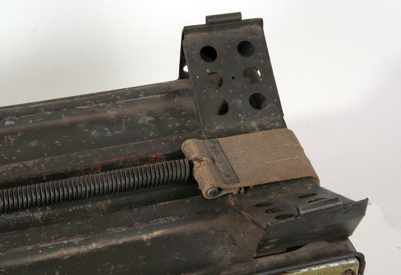
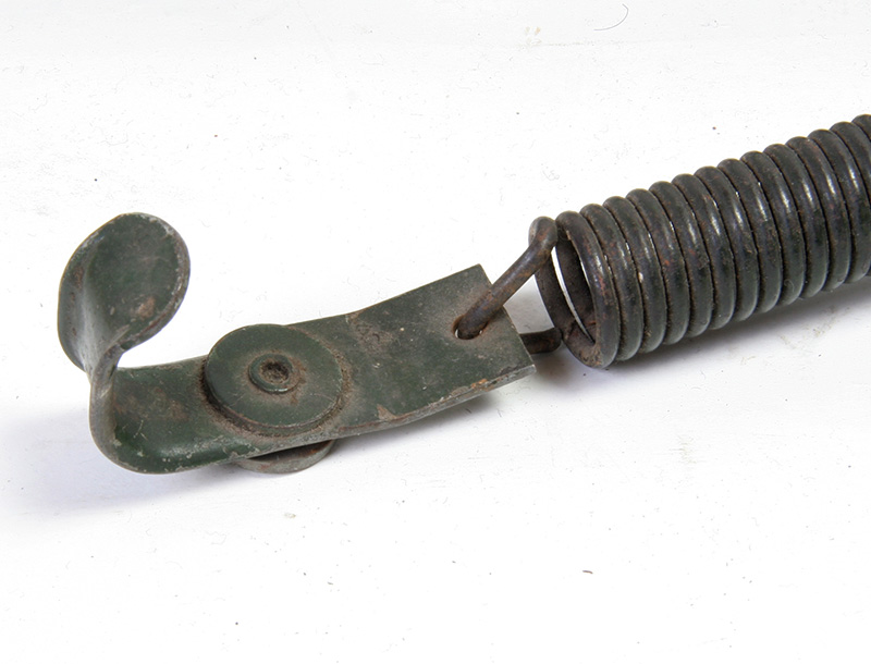
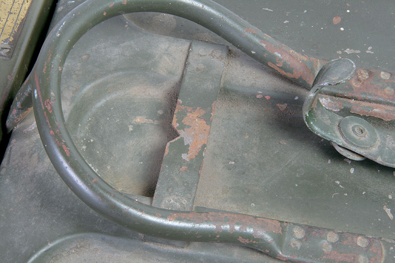
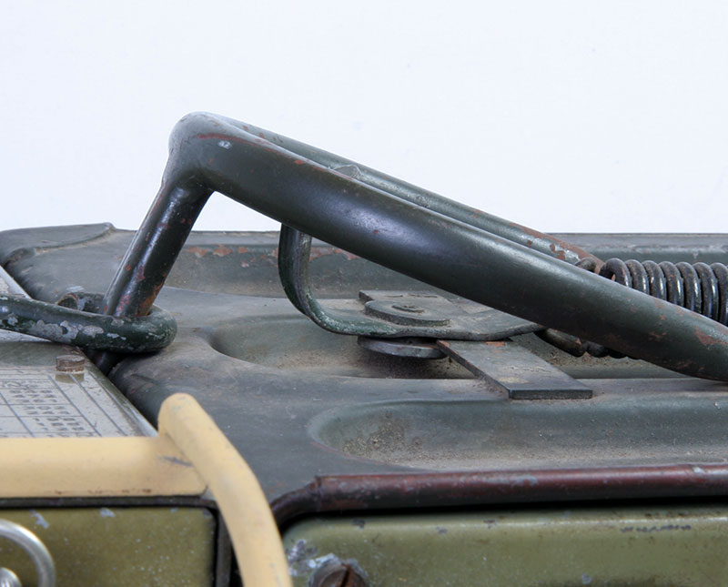
The other side with the bracket to which a kind of cushion is attached.
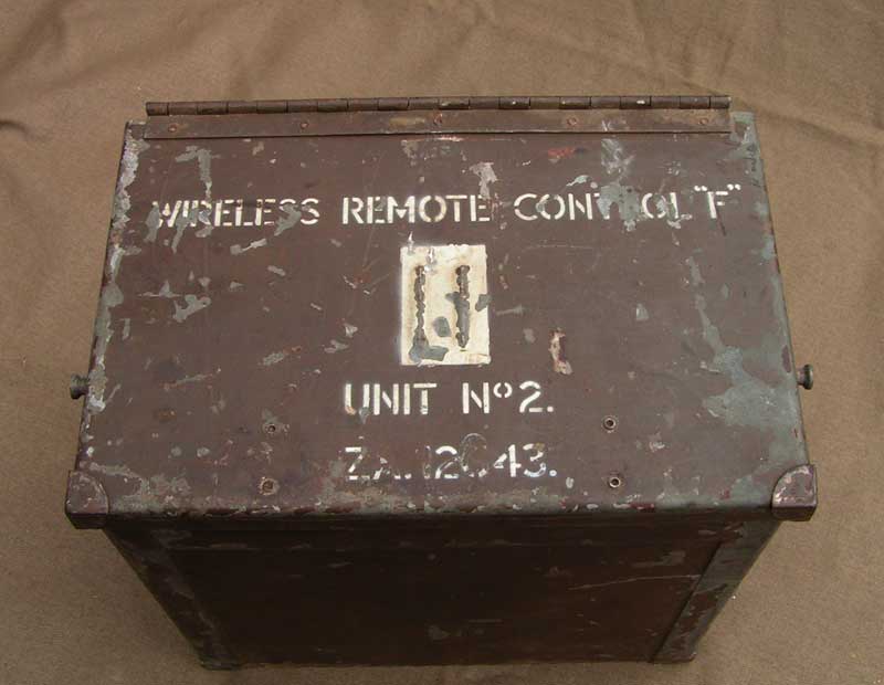
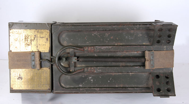
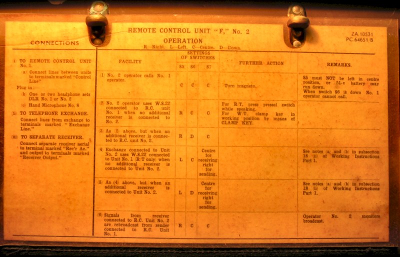
The remote control unit F-No. 2. No. 1, the "nearby" is still lacking.
Visible and you can feel it, No. 2
The modern quick-release on the back, you also come across in the newer "Larkspur" devices.
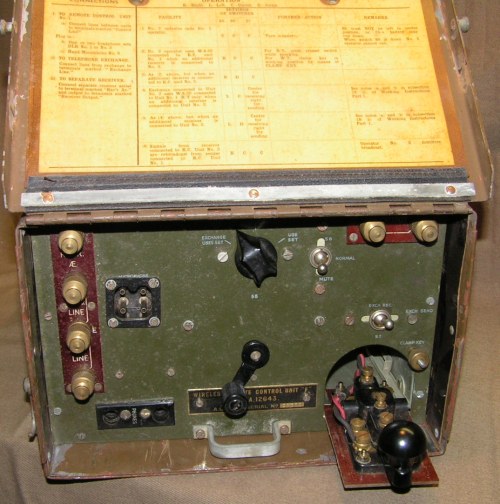
The front cover and extended keyer.
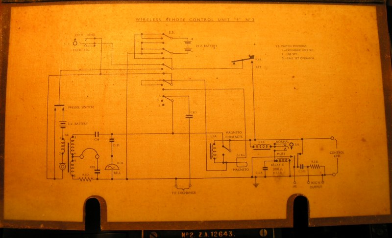
The diagram.
Manual
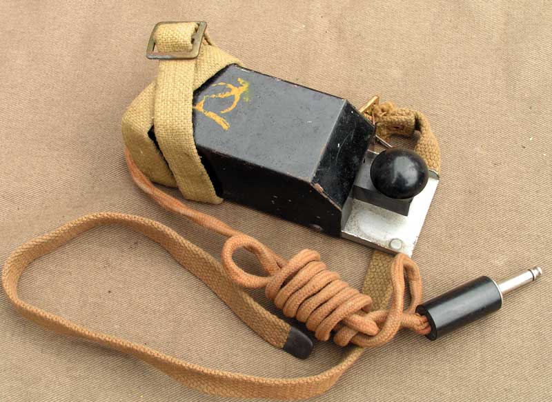
Key
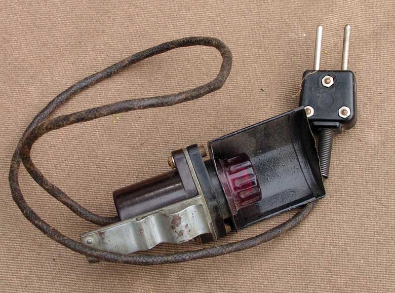
Adjustment-lamp
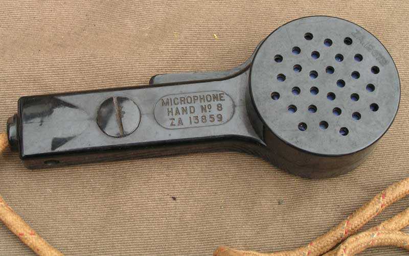
Microphone No. 8.
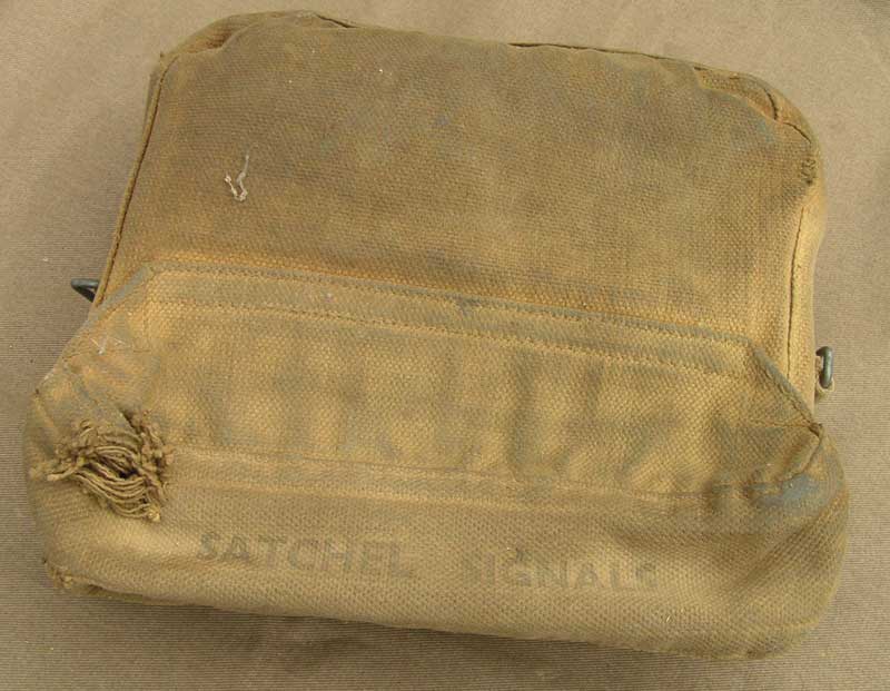
Satchel Signals No. 1
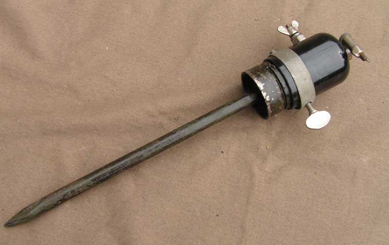
Aerial Base No. 11.
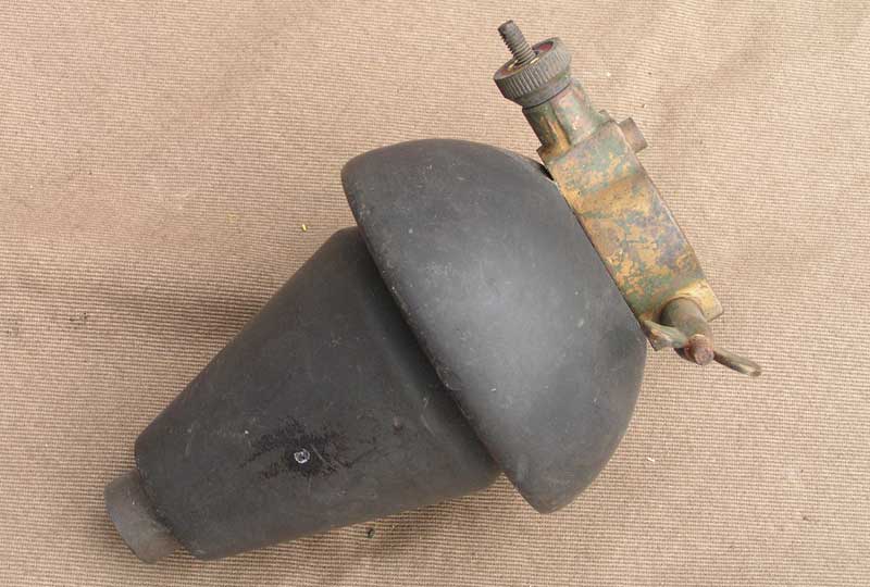
Insulator, W.T. , B
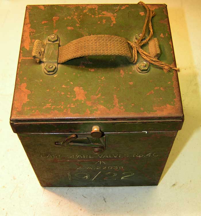
The upper side evan CASE SPARE VALVES No. 4G.
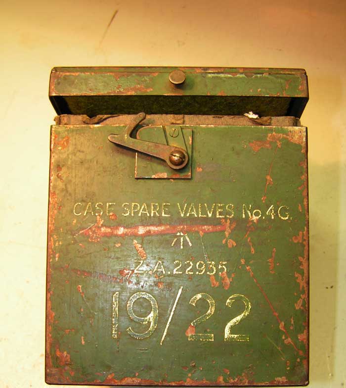
Type Z.A. 22935, for both the WS22 and WS19.
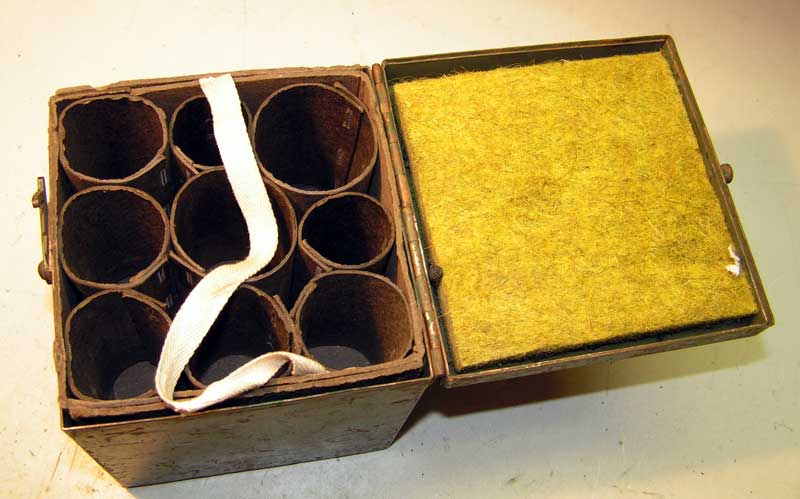
Here they should. But what and where??
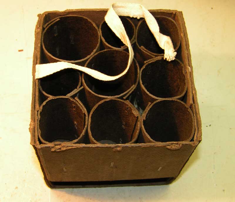
Inside
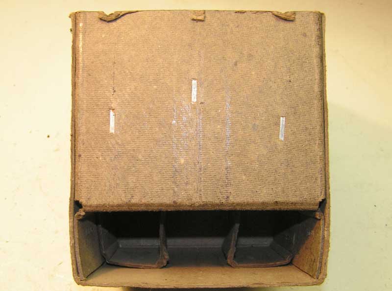
At the bottom of the box also fit three tubes or vibrators?
Here some images from Working Instructions booklet. Original "WS No. 22." This is PART 1, PART 2 I am looking for, who knows anything about this???
Frontpage
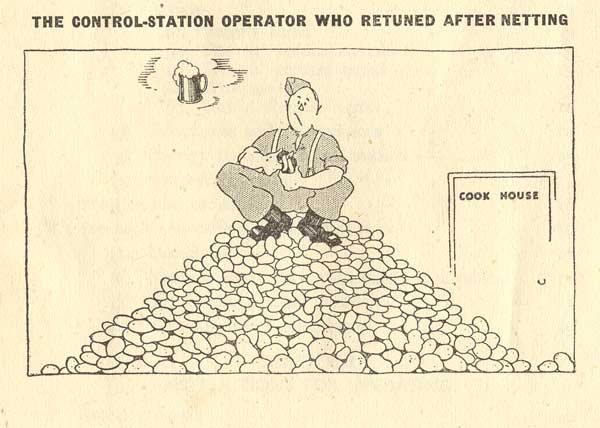
The punishment when retuning after "netting".
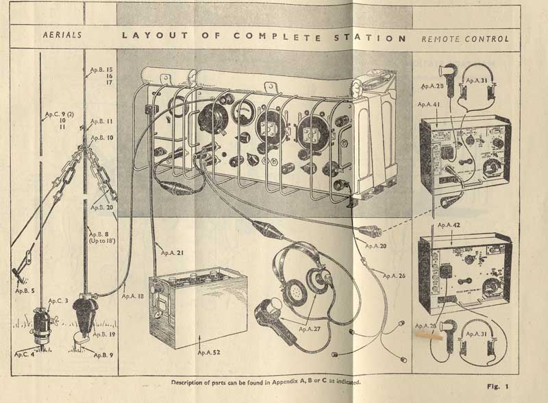
The complete set.
Here again the set, You can not be see the remote controls You'd at least three men need to transport the whole
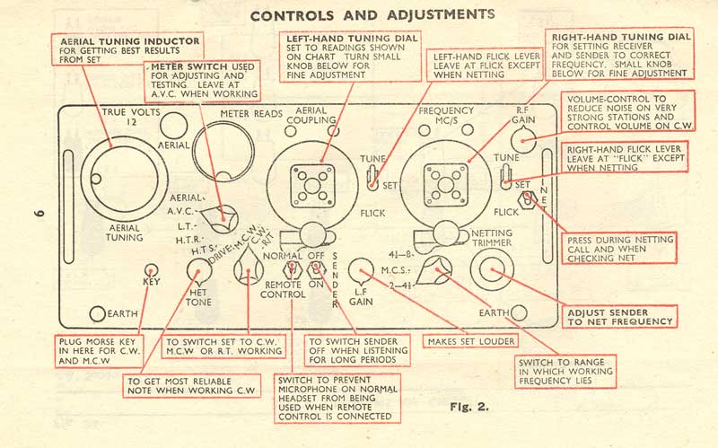
The front panel of the control functions.
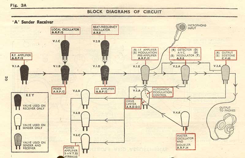
The operation of the "A-sender-receiver" in a very English way drawing.
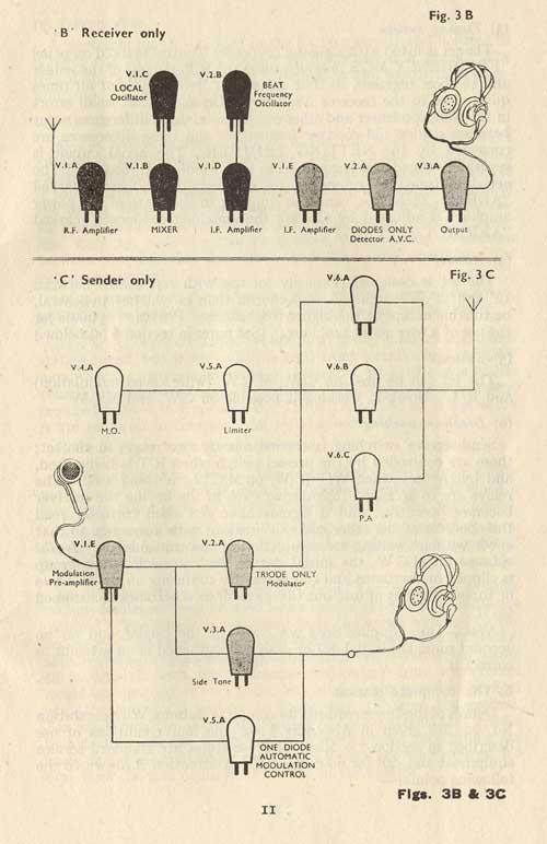
The same,for receiver and sender.
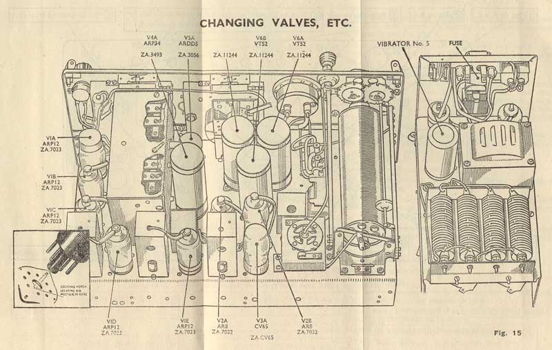
The interior of the WS-22.
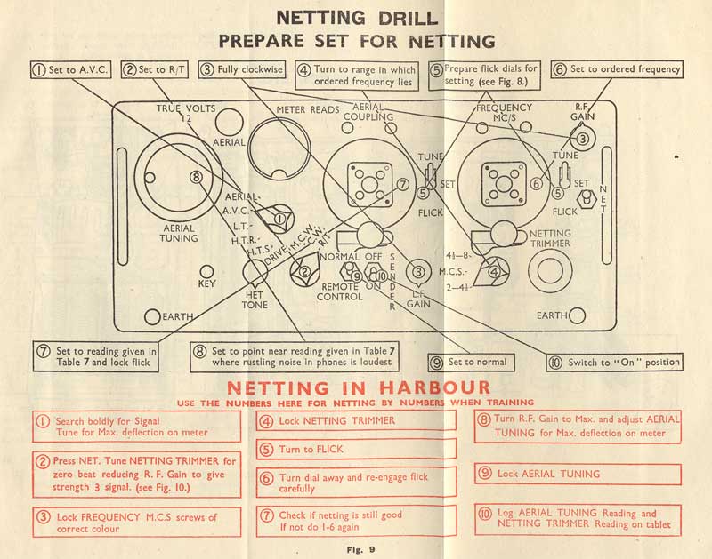
The instruction for the "netting".
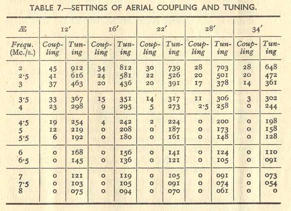
A useful paper, the settings for different antenna lengths.
Here a link to a site with the WS-22 Accessories.
For Jan v.d. R. in A. , Mounting-setails-details of the set on the rack.
Some useful documents for repairing a WS-22.