Het aantal zelfbouwers slinkt nog steeds, maar ik laat me niet door deze trend weerhouden toch nog zo hier en daar wat in elkaar te zetten
De grote uitdaging is nog altijd een VFO met buizen te bouwen die
eenvoudig, maakbaar en toch stabiel is. Wanneer ik dan over stabiel praat gaat het om frequentie verloop van minder dan 10 Hz/uur bij frequenties tot 7 MHz. Dat is nog altijd een hele toer, vooral omdat buizen de vreselijke eigenschap hebben om warm te worden en daarmee allerlei veranderingen teweeg brengen. Maar ja, vroeger moest je een meetapparaat ook eerst een half uur voorwarmen voordat er wat zinnigs mee te meten was. Beter was het de apparatuur helemaal niet uit te zetten. Maar goed, terug naar de VFO.
Uit een tijdschrift heb ik ooit eens het schema van een Harris Cathode-follower oscillator gehaald.
Ik had daar een mooi VFO van gemaakt en er redelijk mee geexperimenteerd met zeer tevreden stellende resultaten. Door de enorme tijdwinst vanwege de "Ophokplicht" door het Corona-virus in Maart 2020, kwam ik op het idee daar nog eens naar te kijken.
Overal zoeken naar het bouwseltje, nergens te vinden...... Weer veel te netjes opgeruimd. Ja, dan maar een nieuwe maken.
Dit is dan de oude, onvindbare uitvoering, laten we hem maar snel vergeten, ik kom hem wel weer tegen wanneer ik wat anders aan het zoeken ben.
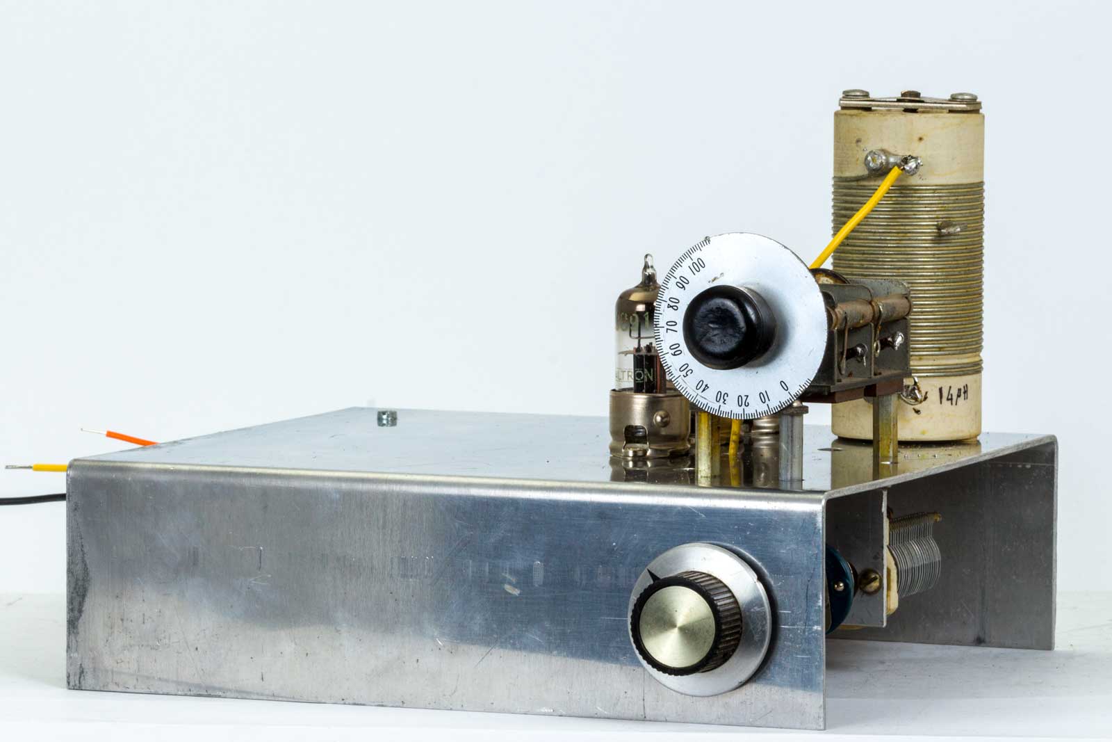
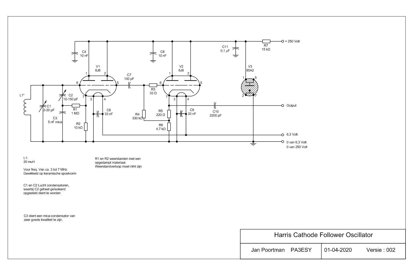
Hier ziet U het resultaat van deze huisvlijt. Het is een ontwerp van een zekere H.E. Harris uit 1951, dat in 1957 door een zekere heer Robert. Ropes gepubliceerd werd in een Amerikaans tijdschrift "Radio and Television News" van Juni 1957, 'A high-stability oscillator circuit' .
De oscillator bestaat uit een dubbeltriode, waarvan de beide helften parallel geschakeld worden. Voor de buis is een 6J6 of ECC91 gekozen vanwege zijn stijlheid van 5,3 mA/Volt, als je dan twee helften parallel schakelt wordt het nog fraaier.
C1 is een normale miniatuur-afstemcondensator van een VHF-ontvanger. Hiermede wordt de gewenste band bestreken. C2 is de band-setting condensator, met lucht diëlectricum een steatiet isolatie en bepaalt met C3 de terugkoppeling. C3 is een mica condensator van zeer goede kwaliteit. De weerstanden R1 en R2 zijn van het stabiele, opgedampte type. Dit is belangrijk, daar andere weerstanden nogal eens de neiging hebben flink te verlopen.
Voor de spoelvorm werd gebruik gemaakt een keramische spoel uit een oude Amerikaanse legerset, de zelfinductie bedraagt ca. 20 muH. De schakeling is nogal gevoelig voor anodespanning-variaties. Voor de stabilisatie dient bij voorkeur gebruik gemaakt te worden van een Philips 85A2, daar hiervan de stabilisatie-eigenschappenheel goed zijn.
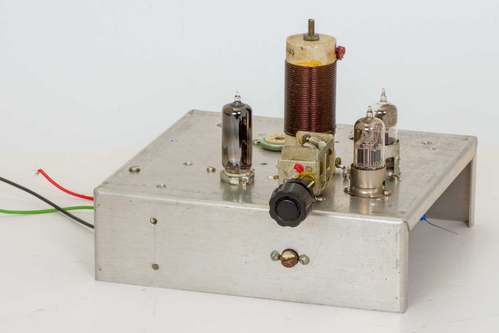
Ziaanzicht van deze stabiele oscillator op een experimenteer chassis dat al vele oscillatoren heeft gedragen. (Met wisselend succes).
De linker 6J6 is de eigenlijke oscillator en de rechtse buis is de kathodevolger die als buffer dient.
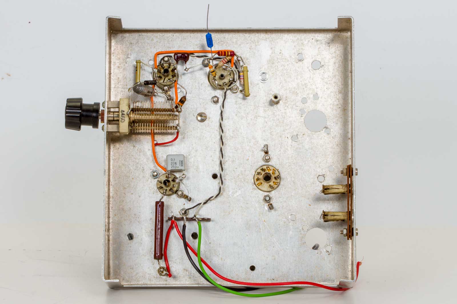
De onderkant met nog ruimte voor een voeding. De meest essentiele verbindingen zijn overal redelijk kort gehouden.
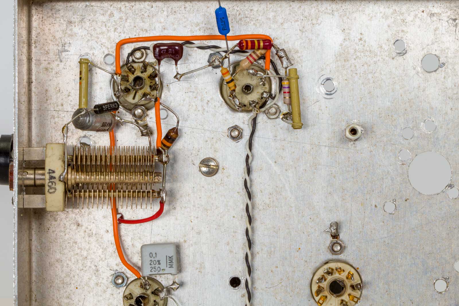
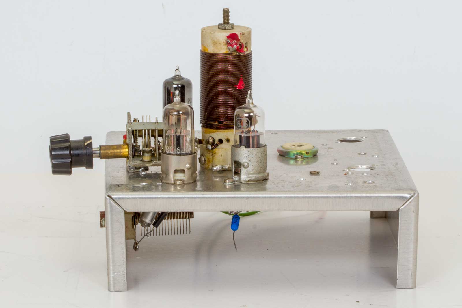
Hier het hoekje waar zich alles afspeelt. Het stelt niets voor maar werkt als een speer.
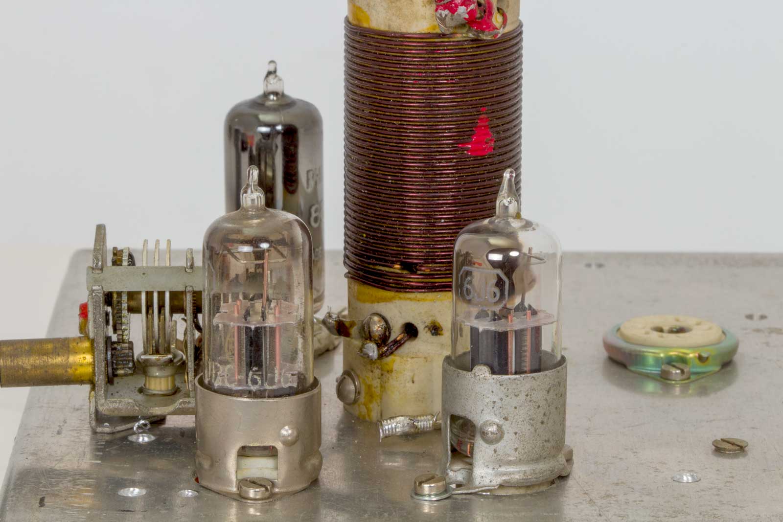
De beide 6J6 (ECC91) buisjes die vroeger in het VHF-AM-tijdperk veel werden toegepast in de beroemde 6J6 balans-converter.
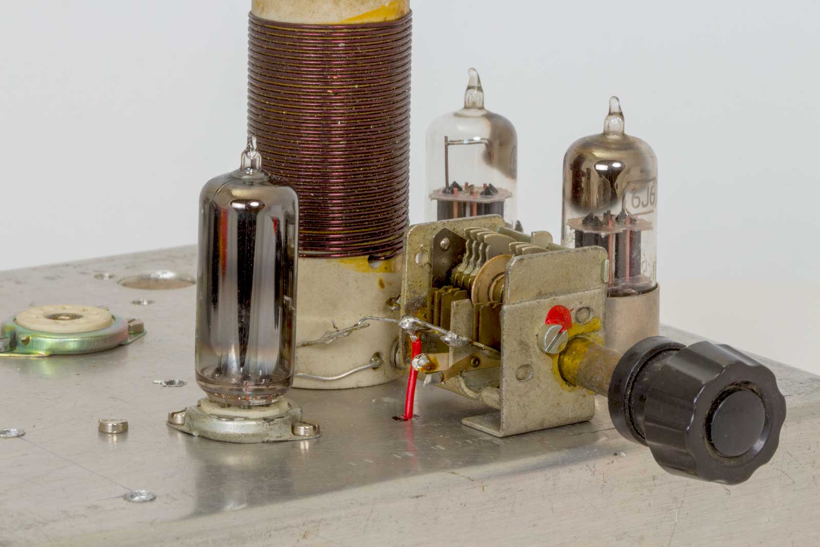
Het kleine afstem-C-tje, Het bereik met deze spoel is van ca. 3480 kHz tot 3850 kHz. De 80 meterband zit er dus keurig in.
Hieronder een beschrijving van de werking, gecopieerd uit een artikel, het is niet helemaal duidelijk wie dit artikel geschreven heeft en de bijbehorende plaatjes ontbreken..
In the still important world of analogue electronics, much basic solid state circuitry can be traced back to the valve era. Developments are often optimised solid-state versions of circuits pioneered in the heyday of valves. For much of that period, there was intense interest in improving the characteristics of tunable LC oscillators: Hartley, Colpitts, Franklin, ECO, Gouriel Clapp, Seiler, Vackar oscillators all had their enthusiastic followers - and all have since appeared in solid state guise.
My interest in one largely forgotten form of oscillator, first described by H E Harris in 1951, was aroused by the Dutch journal Electron (December 1990) which reprinted from its February 1958 issue an article by J J van Gelderen, PA0VGR describing a form of Harris VFO, using a 6J6 valve.
The Electron item led me to Radio & TV News, June 1957 'A high-stability oscillator circuit' by Robert J Ropes; this in turn referred me to J K Clapp's 'Frequency stable LC oscillators' (Proc IRE, Aug 54) providing a detailed survey of a number of LC oscillators and to the original presentation of the cathode-follower family of oscillators by H E Harris in connection with an article on a 'Simplified Q Multiplier' (Electronics, May 51,).
In the Harris oscillators (Fig 1) use is made of the fact that while a cathode-follower has less than unity voltage gain, it has power gain, good phase regulation and presents a very high impedance at its grid. With a valve having a low grid-cathode capacitance this means that full advantage can be taken of the high-Q LC tank circuit with good isolation between the i/p and o/p circuits. In other words, stability is largely determined by the LC tuned circuit.
Fig 1: Two basic forms of the Harris cathode-follower stable LC oscillator.
In effect, a portion of the cathode-follower output is stepped up by passive components and fed back to the grid of the valve to provide the positive feedback necessary to sustain oscillation. In the original application as a (regenerative) Q-Multiplier, it gave controllable selectivity of a very high order with excellent stability: Fig 2. The later applications, developed by Ropes and PA0VGR, showed that the basic Harris ideas could usefully be applied to HF VFOs for amateur radio, providing a stable output that can remain constant over wide variations of the LC ratio, a characteristic that cannot be achieved with the conventional high-C Colpitts oscillator.
Fig 2: The simplified 100kHz Q-Multiplier described by H E Harris In Electronics (April 1951) using regenerative cathode-follower stage to provide variable selectivity.
R J Ropes dubbed his version a 'Class A Colpitts' (more precisely Class AB) but pointing out that it differs radically from the conventional Colpitts oscillator: "Since the oscillator operates in Class AB, no grid current flows during any part of the oscillatory cycle, there is no 'grid-leak' capacitor and no grid-bias voltage is produced by grid-current flow, as is the usual case in a Class C oscillator."
He also noted that: "As pointed out by Clapp, the frequency coefficient of an oscillator is independent of the LC ratio if the operation of the circuit is linear, that is Class A, AB or B. Since Class A operation of an oscillator is, for all practical purposes, impractical, Class AB or B operation must be used to give the necessary linearity of oscillation."
As with other Colpitts, Hartley, ECO type oscillators, maximum stability is obtained when the capacitive divider or inductive tapping is as close as possible to the earthy-side of the tank circuit while still providing the necessary feedback. With capacitive tapping, this implies making the lower capacitor of higher value than the capacitor connected to the grid. It should be noted that R1 (Fig 3) provides the positive feedback and is not intended to pass DC in the manner of a grid leak. For Q-multipliers, the degree of positive feedback and hence the onset of oscillation can bu controlled by making this resistor variable. Active devices should have reasonably high gain and low input capacitance. Ropes used a 6J6 twin-triode with both sections in parallel. PA0VGR's circuit shows only a single section of the 6J6.
Fig 3: A Harris cathode-follower oscillator used for a 3.5MHz VFO by R Ropes and adopted also by PA0VGR. The Ropes design used both sections of the 6J6 dual-triode with 150V (regulated) HT (anode current 1.2mA) covering 3.5 to 4MHz (approximately 90% rotation of the 25pF tuning capacitor) with L 21µH (24 turns No 22, enamelled copper wire closewound on 1.25" diameter former).
Overigens waren deze artikelen en nog veel meer interessant spul uiit oude Electrons op de site van Rob Kalmeijer te zien:
Zeer de moeite waard!!, jammer genoeg zijn er nog maar een paar artikelen over.
De lovende woorden over de oscillator komen redelijk overeen met mijn ervaringen met deze schakeling. Ik dacht nog slim te zijn en de uitkoppeling naar de uitgangsbuffer van de kathode van V1 te halen, dit bleek toch niet zo'n geweldig idee, dus weer terug vanaf het rooster van V1.
Het schema:
Aangezien de artikelen van Rob Kalmeijer niet meer on-line staan heb ik nog wat speurwerk verricht met het volgende resultaat:
Het artikel van Robert J. Ropes in een oude "Radio & TV News" van juni 1957 in pdf.
En een Google-vertaling van dit artikel, Nederlandse versie, met veel grammatica- en taalfouten.
Simplified Q-multiplier by H.E. Harris uit Electronics may,1951