Thanks to Steve Rawcliffe, G4YXU for his excellent translation of the WS-46 pages.
Yes, it’s a Wireless Set No. 46!
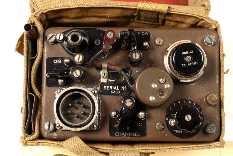
Loads of these were manufactured, and loads were scrapped or chucked away. I got this one for free. Yep, free. And I’m pretty happy about it! The set was designed in 1942, specially for landings. It can be used on voice and CW. The transmit/receive button also acts as the morse key. Maximum speed on CW: 12 wpm.
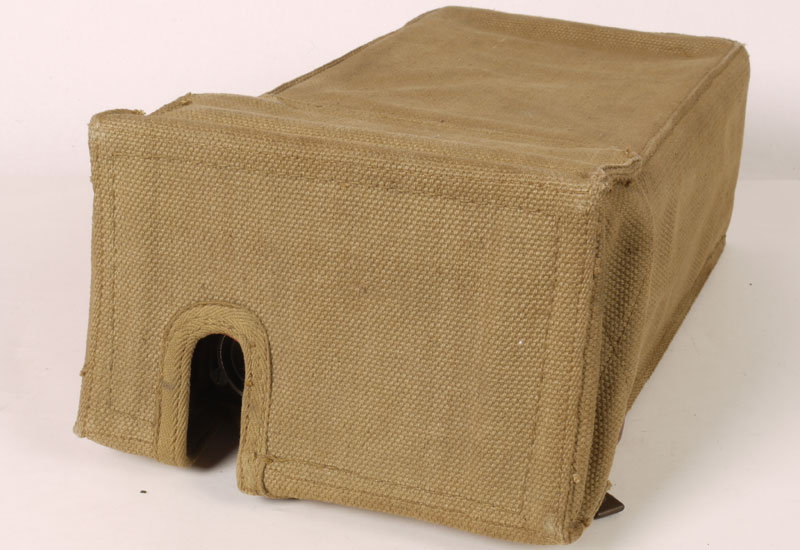
Neatly stashed away in its cover.
A better view of the key.
Frequency ranges:
Range 1: 3.4 - 4.3 MHz
Range 2: 5.0 - 6.0 MHz
Range 3: 6.4 - 7.6 MHz
Range 4: 7.9 - 9.1 MHz
Valves
Transmitter :
Oscillator: ATP4
Modulator: ARP37
Valves Receiver :
Mixer/local oscill.: ARTP2
1. IF: ARP12
2. IF + reflex. LF amplifier: ARP12
Detector and AVC: AR8
IF: 1550 kHz.
Power requirements
Anode: 150 V
Heater: 3 V
Modulator: -12 V
Range: About 8 – 10 miles, depending on conditions and antenna.
Weight:
Set alone: 11 lb.
With batteries, etc.: 24 lb.
Operation is extremely simple. It had to be, as the operator was going to have other things to worry about than tuning and netting while on a beach under fire!
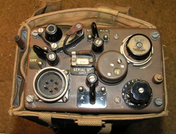
The transmit button is top right. Under that and to the left is an indicator that allowed the antenna trimmer to be set correctly. The cap contains a bulb that can be connected to the antenna socket. Very clever.
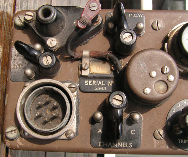
This photo shows the antenna connector. Just above the serial number you can see a window containing an on/off indicator.
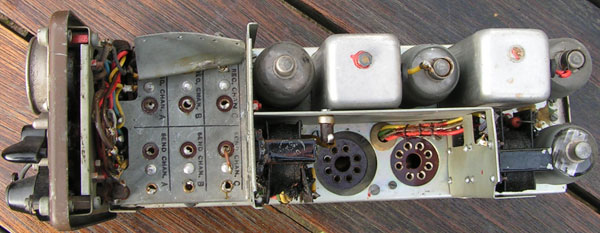
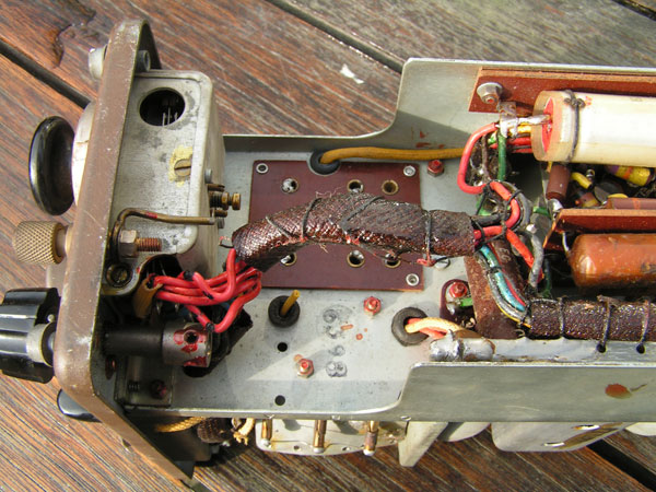
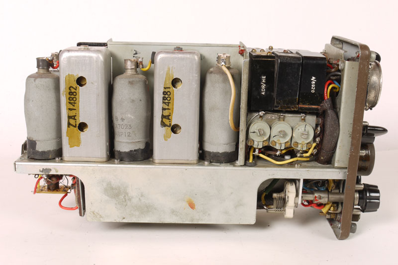
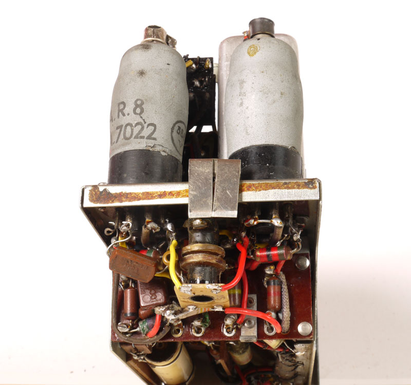
View from above. The ATP4 and ARP37 valves are still missing.
With all valves and crystals in place.
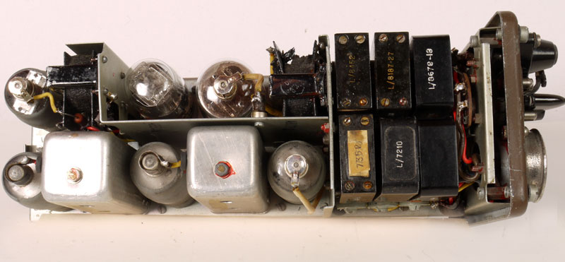
Transmitter side, showing the transformers.
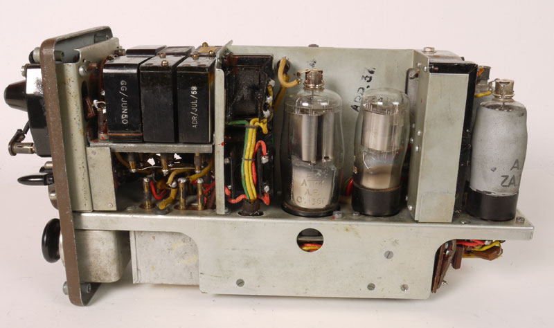
With all components in place.
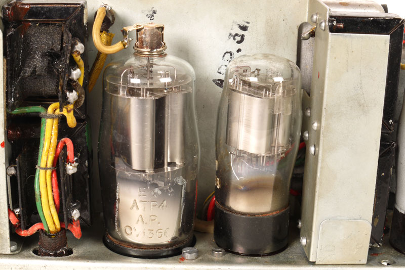
The two transmitter valves. The ATP4 is on the left, and the ARP37 (which is difficult to get hold of) is on the right.
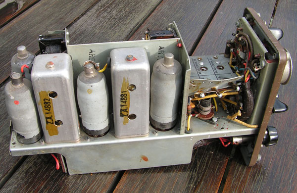
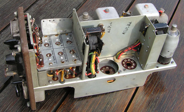
The receiver side.
The aerial trimmer is still missing, and the crystal unit still needs some work.
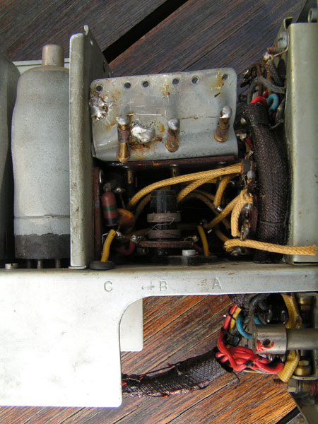
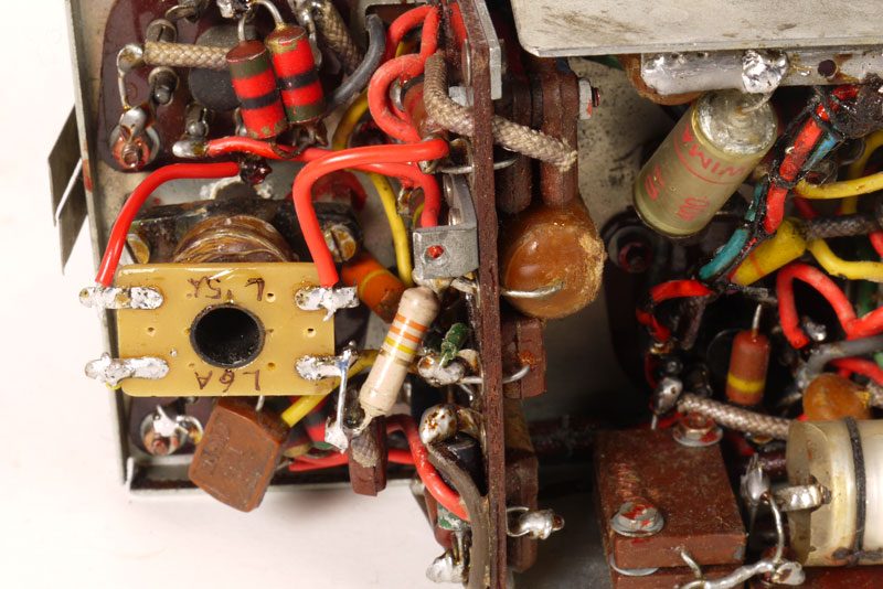
View from underneath. The connectors in the brown plate are for the plug-in coil (one coil per range).
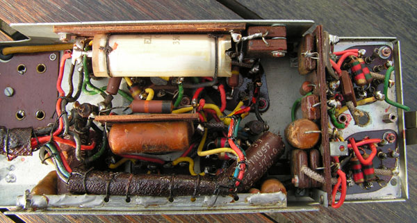
The rest of the underside. The third IF transformer is still missing from the left-hand side of the photo. Will have to find a solution of some sort.
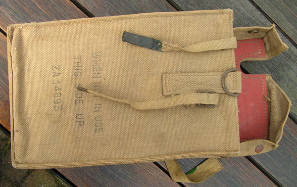
The whole thing, including the aerial rods, is carried in this webbing pouch.
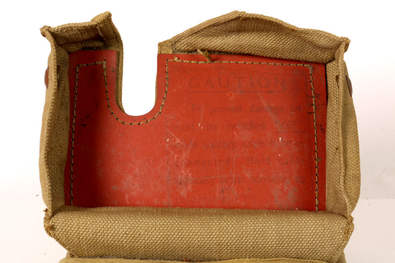
You can still read the instructions in the lid.
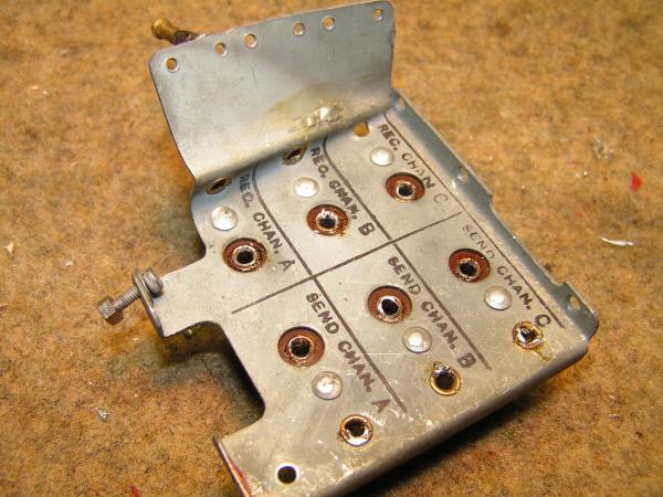
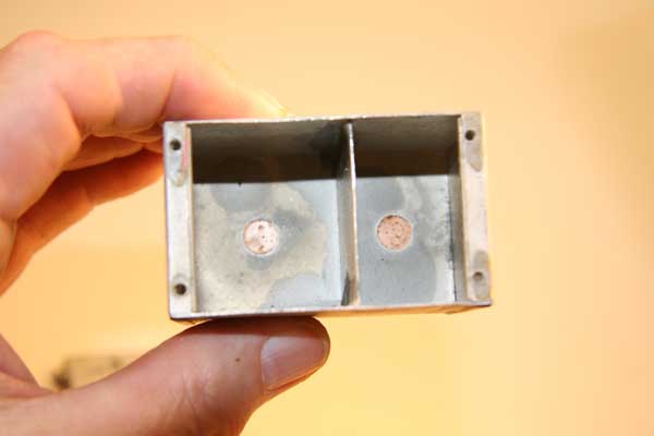
Got this piece of metal out. Now I have to fix it. The holes at the top are for the three trimmers.
Right. Now what?
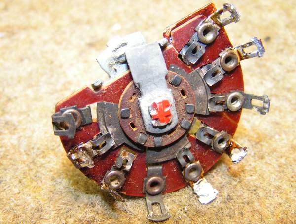
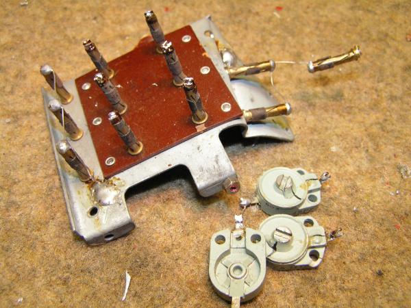
The on/off switch didn’t survive the dismantling process.
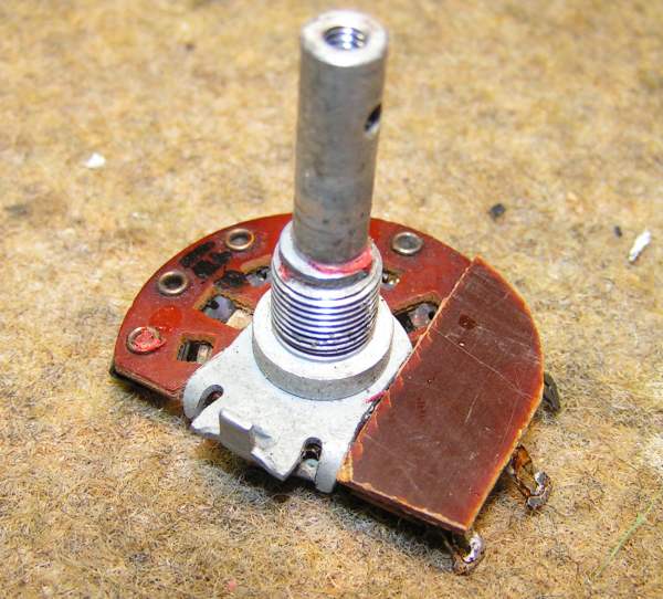
Fixed. Won’t be visible later.
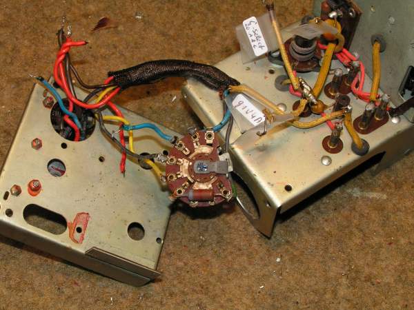
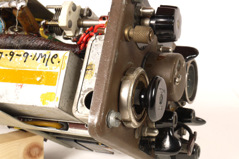
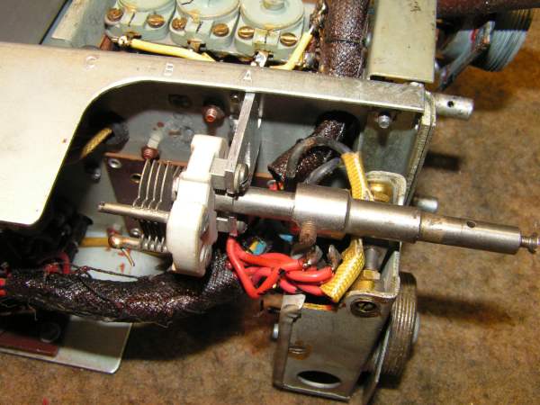
Stuck a few labels on here and there. It would be nice to be able to reassemble the thing later. The picture above also shows the wires which (as I found out in 2011) had got swapped over. I shall be carrying on with this project, and hope to have the set working by 2007. I’ll keep you up to date.
Stuck a few labels on here and there. It would be nice to be able to reassemble the thing later. The picture above also shows the wires which (as I found out in 2011) had got swapped over. I shall be carrying on with this project, and hope to have the set working by 2007. I’ll keep you up to date.
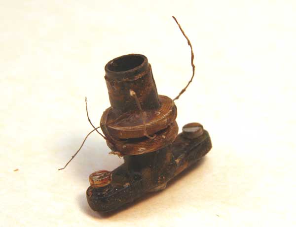
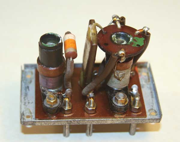
The repaired crystal unit and its trimmers.
Fitted two crystals for the “White Range.” The colour is correct, but the frequency is not, as the cases are empty. But there’s enough space inside to install the crystals.
The trimmer.
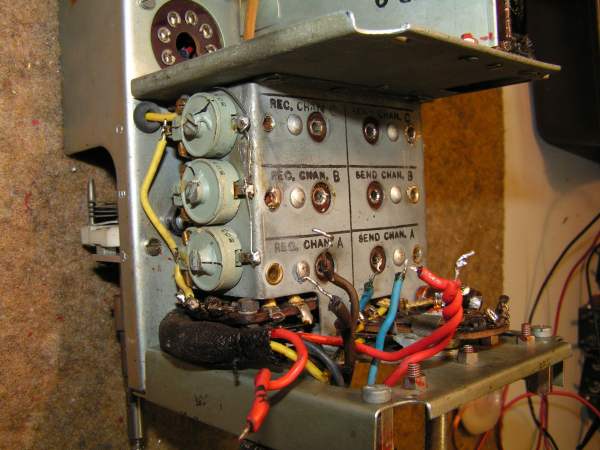
The receiver side with the repaired crystal unit.
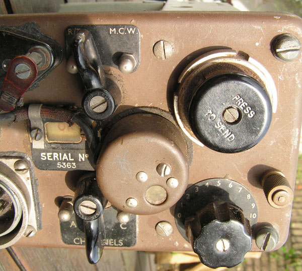
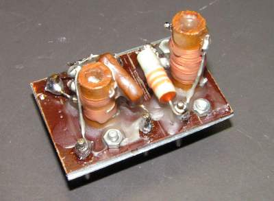
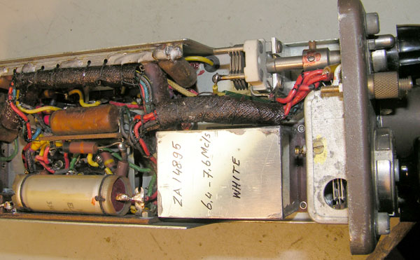
And here’s the cleaned-up front panel. In the meantime, I’ve also made a start on the coil unit. I decided to make one myself, for Range 2 (6.4 MHz to 7.6 MHz). This is the “White Range” with the number ZA 14895.
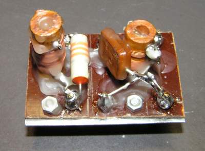
The coil on the right is the 20 μH oscillator, with the 4.7 μH input and tank coil on the right. The unit has been tropicalized using candle wax.
Another angle. The divider and the can are still missing.
View from underneath.
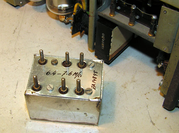
The coil unit in its can. Very difficult to open up again, so I hope everything’s OK inside. Didn’t test it, which was a bit daft.
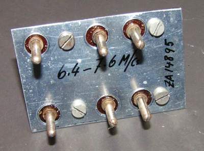
This is what it looks like from below.
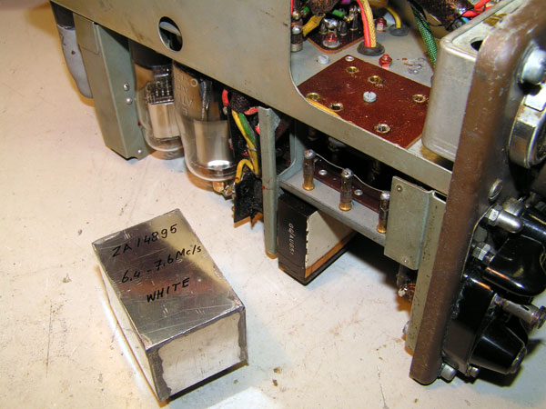
And here you can see how the unit fits into the case.
An original coil set.
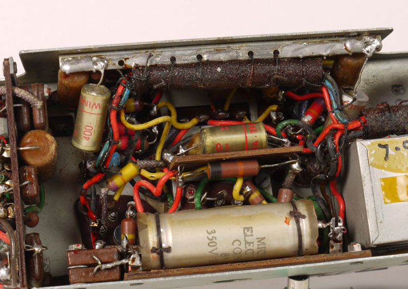
View from underneath. I’ve replaced the 0.1 μF capacitors. Added a few more components. Thanks to Louis Meulstee, who had a few components lying around, I now finally have the third IF transformer.
Also managed to get hold of a coil unit and a crystal, again thanks to Louis. These were on sale at the famous Rosmalen 2008 radio fair. The seller was also the source of my beautiful T1154 microphone plug, but I had completely missed his stand!
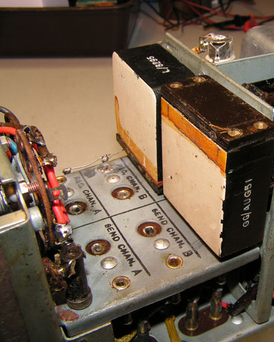
Almost exactly three years later, just before the 2011 Rosmalen radio fair, I finished assembling the third IF transformer.
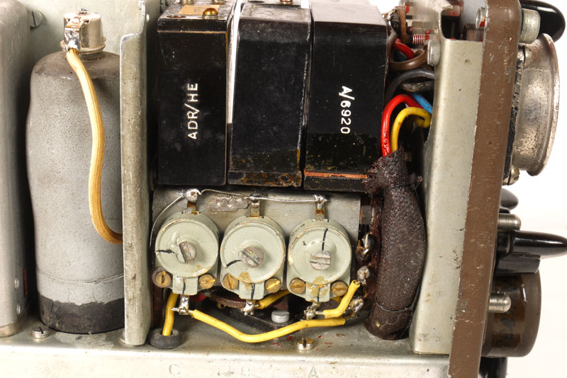
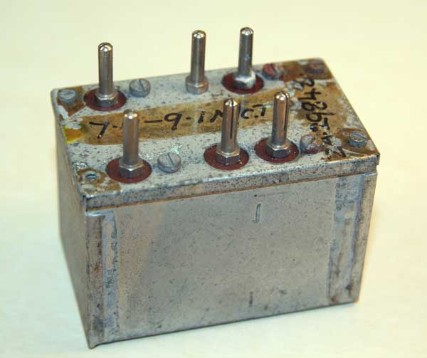
Another view of the IF transformer, with the connector plate on top.
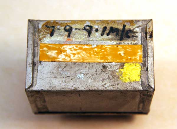
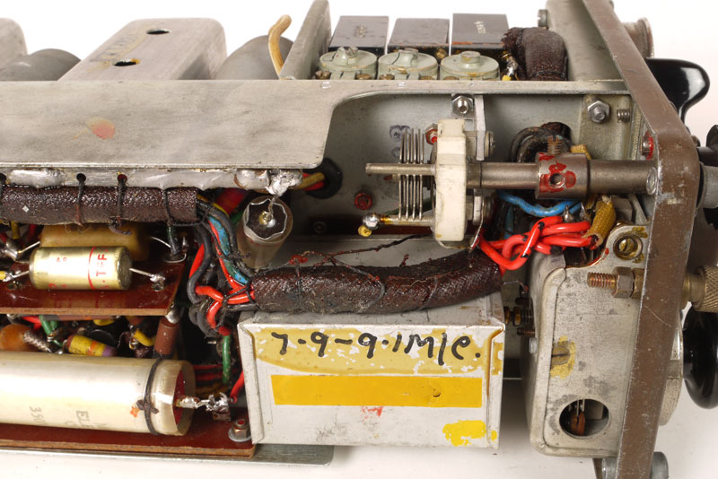
This is the “Yellow Set” (7.9 MHz to 9.1 MHz).
And this is how it looks from underneath.
Inside view. The coils are adjustable. I’m going to dismantle my homebrew coil unit and convert it to the “Red Range,” which lies in the 80-metre band.
On this photo you can clearly see that the yellow tape hides two holes, which are used for aligning the set.
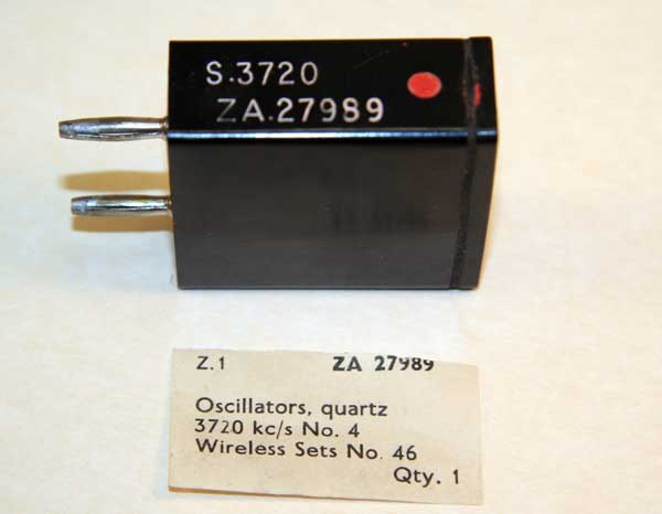
The 3720 MHz crystal in its original packaging, date 25 October 1944. Air Ministry or Army ???
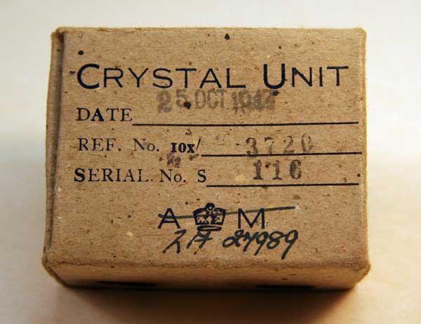
Air Ministry or Army ???
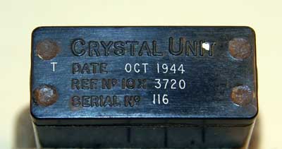
A low serial number.
6 March 2011
Following the successful renovation of the WS 18 transmitter, I got the WS 46 out on the bench again. As I mentioned above, I’d got hold of the third IF transformer two years previously, but I still had to connect it, and it wasn’t clear how that was supposed to be done. It was quite a puzzle, and all the more so because the previous owner hadn’t just cut the transformer free – he’d changed various bits of the wiring.
Very little of it was correct, so I got out the circuit diagram and rebuilt it from scratch. Made up a connector plate for the transformer and let it dry overnight. The two windings are different … which was the primary and which was the secondary? I just had to guess.
Connected up the plug on the front, found a couple of crystals and applied power. Sounds came out of the headphones.
Set the signal generator to 1550 kHz and adjusted the third IF transformer for maximum reading. Looked like I’d guessed right.
Then I checked the receive frequency. Something wasn’t right … should have been 1550 kHz above the crystal frequency, but it was much higher. OK, come back to that later. Let’s see if the transmitter works. No, the supply voltage sank like a stone. Took a look at the circuit diagram, and worked out that there was only one real suspect. But where was he? After carefully studying the drawings I worked out that it was directly behind the front panel, behind a plate.
So off come all the knobs and the front panel, which is quite a job. The capacitor had indeed failed, so I replaced it with a more modern type.
Put everything back together again and held my breath as I pressed the transmit/receive knob. The voltage didn’t drop, but the set didn’t transmit either.
So I decided to see why the receiver frequency was so high and why the set needed the transmitter crystal in order to receive. That’s when things became clear: the wires from the crystal selector switch had got swapped over when the thing was being repaired. Time for a break.
WS 46 33 / 33
Took my time and hunted down some more documentation, including data for the third IF transformer. Now I knew what was primary and what was secondary.
Next day, took everything off the front panel again, but this time I also removed the switches and unscrewed the crystal unit. Swapped over the TX/RX selector wires. The way they were connected was pretty logical – the longer wire was connected to the more distant contact, while the shorter wire was connected to the nearer one. But I swapped them over anyway – the wires were just long enough. Then put everything back together again. What a job!
Then I checked the IF transformer. Which, of course, was connected the wrong way. Fixed that and applied power again.
Yippee, noise coming out of the headphones and the RX crystals are now determining the receive frequency, everything is as it should be. Plugged in another crystal. And the heater current failed. Oh no … have I blown all the heater filaments?!? Checked everything. Valves OK. So what’s the problem? The send/receive switch maybe?
It turned out that the blue wire carrying the heater current from the on/off switch had broken off at the RT/MCW switch. Oh dear, am I going to have to take off the whole front panel again, or is there another option? Turned out there was – could just get the tip of the soldering iron through a hole to reach the tag.
Passed the new wire through another hole and soldered it into place. Power on and … yes! Everything worked. Even the antenna current indicator lamp lit up. Terrific!
Still missing: junction box, aerial rods, headset with throat microphone, the correct crystals and a battery box with pouch.
So you’ll just have to be patient for the next instalment.